
Interconnection circuit between two loop antennas embedded in a wristband of a wrist-carried wireless instrument

A technology of wireless devices and loop antennas, applied in variable reactance loop antennas, antenna support/mounting devices, independent non-interactive antenna combinations, etc., can solve non-optimal antenna efficiency and non-optimal noise matching And other issues

Inactive Publication Date: 2006-01-04
ETA SA MFG HORLOGERE SUISSE
View PDF1 Cites 15 Cited by
  • Summary
  • Abstract
  • Description
  • Claims
  • Application Information

AI Technical Summary

Problems solved by technology

[0007] However, the solution according to document US 5,986,566 still has some deficiencies
Measurements of the above antenna structures show that the antenna efficiency is not optimal and the noise matching is not optimal

Method used


Image

  • Interconnection circuit between two loop antennas embedded in a wristband of a wrist-carried wireless instrument
  • Interconnection circuit between two loop antennas embedded in a wristband of a wrist-carried wireless instrument
  • Interconnection circuit between two loop antennas embedded in a wristband of a wrist-carried wireless instrument

Examples


Embodiment Construction

[0016] As mentioned above, the present invention relates to a wrist-portable wireless device for receiving radio frequency signals using a wireless data transmission system in the frequency band of 30 to 300 MHz, specifically in the frequency band of 88 to 108 MHz. The invention relates more precisely to an antenna structure with optimized antenna efficiency.

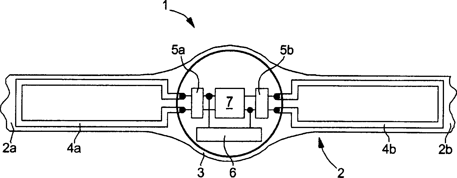
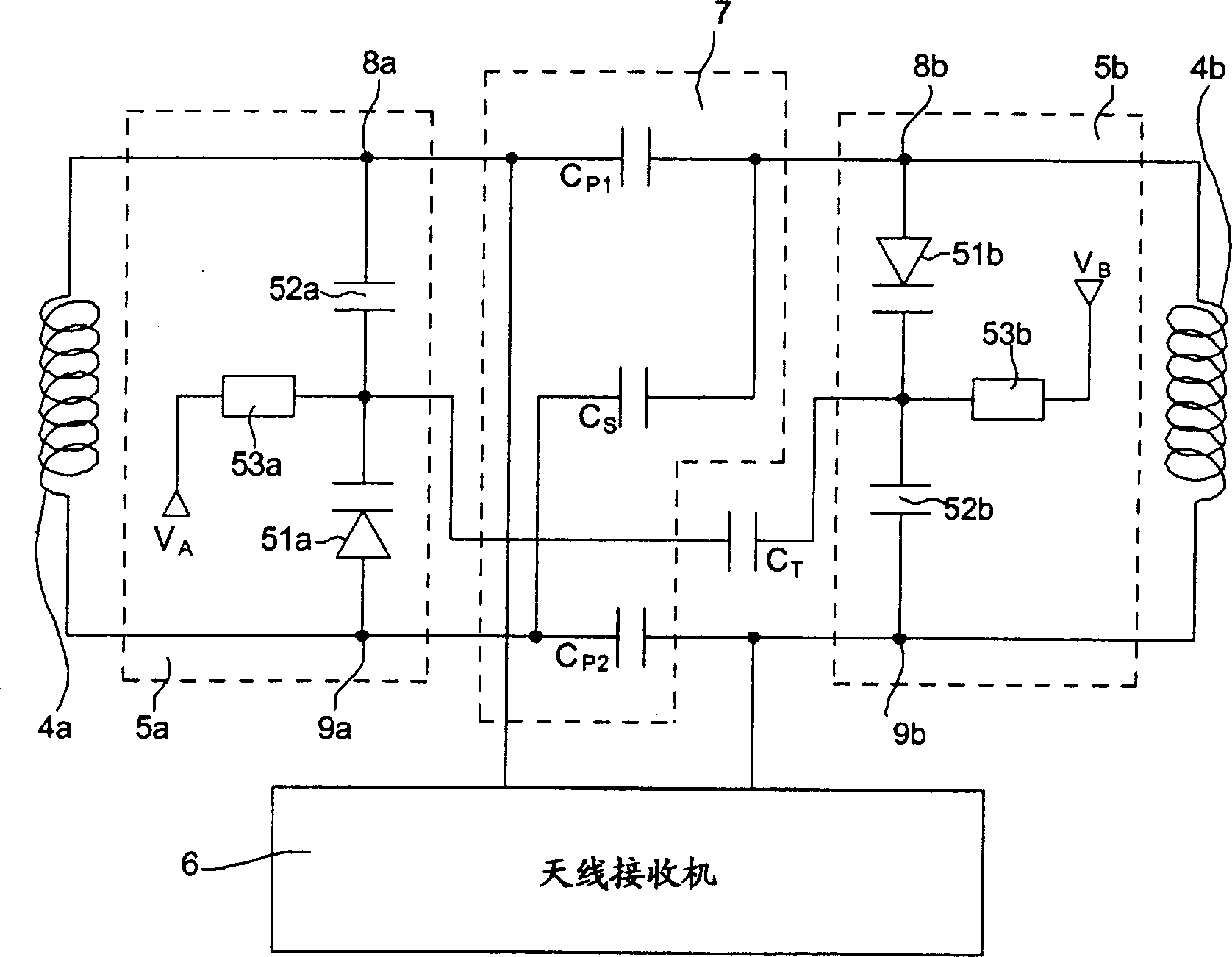
[0017] First refer to figure 1 , shows a cross-sectional view of a wrist-worn wireless device. The wireless device 1 includes a wristband 2 having a first wristband part 2a and a second wristband part 2b connected to opposite sides of a housing 3, each wristband part having an upper surface and a lower surface. The first loop antenna 4a and the second loop antenna 4b are embedded in the first wristband part 2a and the second wristband part 2b, respectively, and extend between the respective upper and lower surfaces. The loop antennas 4a and 4b are respectively connected to the first tuning circuit 5a and the second tu...


PUM


Abstract

The invention relates to a wireless instrument (1) comprising a wristband (2) having a first (2a) and a second (2b) band portions connected to opposite edges of a casing (3), each of the first and second band portions having upper and lower surfaces. A first (4a) and a second (4b) loop antennas are embedded respectively in the first and second band portions and extend between the corresponding upper and lower surfaces, both loop antennas being connected through the opposite edges of the casing to a first (5a) and a second (5b) tuning circuits, the first and second tuning circuits are connected to an antenna receiver (6) arranged in said casing and together in a hybrid manner via an interconnection circuit (7), both tuning circuits being connected partially in parallel and partially in series.

Description

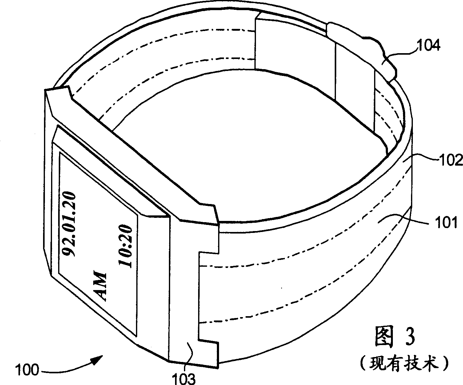
technical field [0001] The present invention relates to wrist-portable wireless devices, and more particularly to a wristwatch receiver having a magnetic loop antenna embedded in its wristband. In the following description, a loop antenna may be understood as a single loop of wire lying substantially in the same plane, the normal operating frequency of which gives a substantially uniform current along the wire. Background technique [0002] In recent years, wireless devices with antenna systems embedded in wristbands to receive radio frequency signals have become common. Many prior art solutions disclose antenna arrangements of circumferentially variable size embedded in wristbands for use with radio equipment worn on a person's arm. Thus, the antenna can be made long enough to receive signals at frequencies beyond the VHF band (30-300 MHz). As shown in FIG. 3, the loop antenna 101 can be formed in a single way in the wristband 102, which is connected to the housing 103 of...

Claims


Application Information

Patent Timeline
IPC IPC(8): H01Q1/27H01Q1/22H04B1/08H04B1/18G04G21/04
CPCH01Q7/005H01Q1/273H01Q21/28H01Q1/24
Inventor M·比斯格
Owner ETA SA MFG HORLOGERE SUISSE
Learn More