Roller blind assembly for side window

A rolling shutter, car window technology, applied in door/window protection devices, windows, windows/doors, etc., can solve problems such as increasing space, and achieve the effect of reducing space and compact structure

Inactive Publication Date: 2011-09-07
BOS
View PDF1 Cites 0 Cited by
  • Summary
  • Abstract
  • Description
  • Claims
  • Application Information

AI Technical Summary

Problems solved by technology

[0008] In previous solutions, the two roller blinds for the quadrangular window area and for the triangular window area were far apart from each other, which required additional space for the designer

Method used


Image

  • Roller blind assembly for side window
  • Roller blind assembly for side window
  • Roller blind assembly for side window

Examples


Embodiment Construction

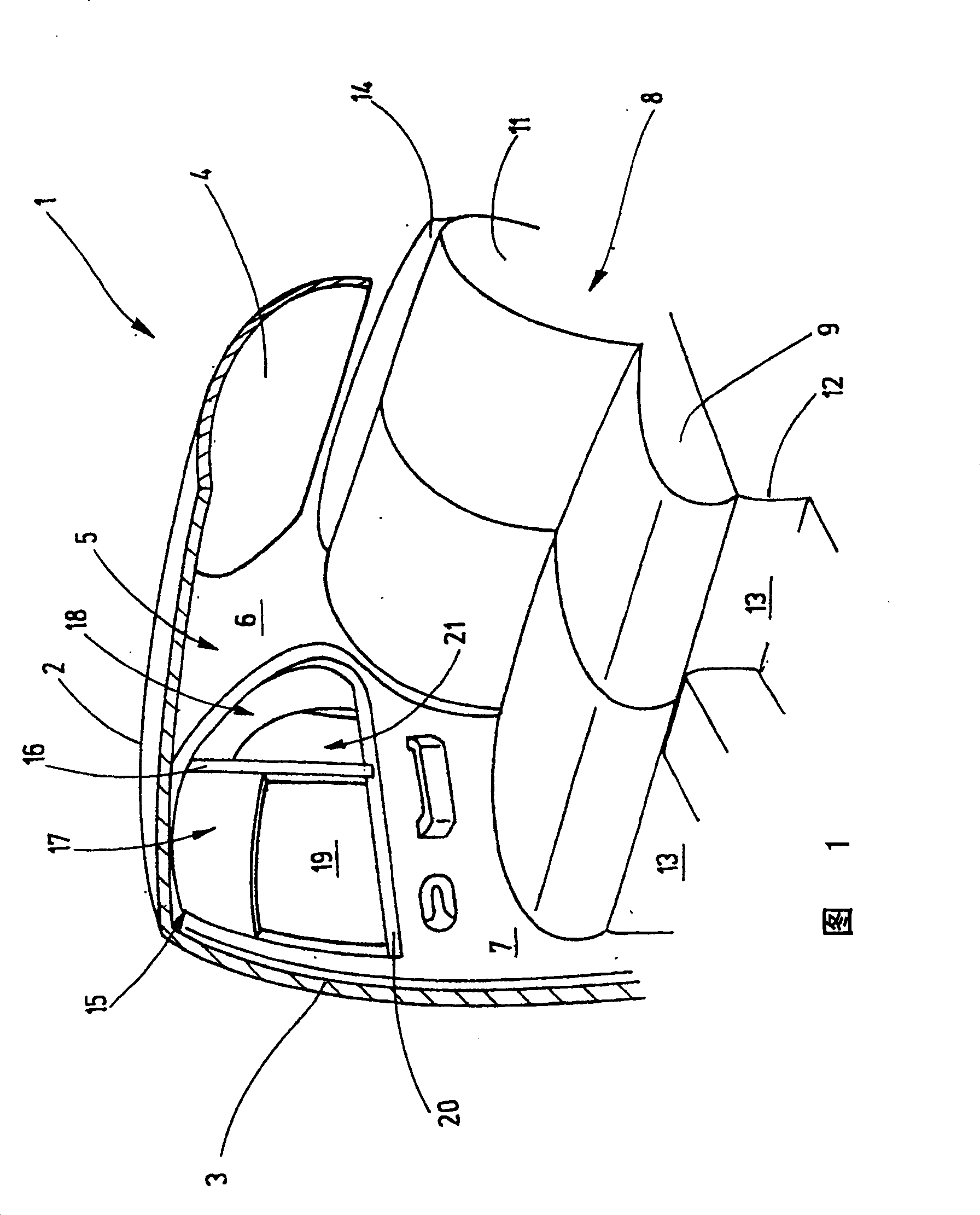
[0029] figure 1 A partial cutaway depicting the rear seat area of ​​a car. The viewing direction of this figure is the right inner side, which is mirror-symmetrical to the left inner side, not shown. The view is simplified, for example, the internal structures of the bodywork such as reinforcements, fastening means are not shown, since their description is not necessary for understanding the invention. The description of the bodywork is also simplified and the cavities that exist there are not visible.

[0030] The body part 1 shown has a roof 2 from which a B-pillar 3 extends laterally downwards to a floor assembly (not shown). As you can imagine, there is also a corresponding B-pillar on the cutaway side of the car. The roof 2 merges at its rear edge into a rear window 4 . The rear window ends laterally on a C-pillar 5 , which is at a distance from the B-pillar 3 . The C-pillar 5 supports an interior trim 6 .

[0031] A right rear side door 7 is hinged on the B-pillar ...


PUM


Abstract

The invention provides a window-side rolling blind device, consisting of two rolling surfaces which wind around two independent reels. The reels are arranged with a setting angle to each other and correspond to the guides. In order to save space and correctly fix the rolling surfaces at the meeting position, a central piece is used, which is provided with a pedestal for the reel shell of the two rolling surfaces and a pedestal for the guide of the two rolling surfaces meeting at the position. Besides, the casing of a thrust component is fixed in the central component.

Description

technical field [0001] The invention relates to a side window roller blind device. Background technique [0002] With the increasing comfort requirements of motor vehicles, the extensive shading of side windows in motor vehicles is also required. This is especially difficult for side windows which are divided into several regions. The side windows of an ordinary sedan are an example. Here, the rear side window is divided into an at least approximately trapezoidal or rectangular area and an at least approximately triangular area. Shading of quadrangular areas is usually not a problem anymore. [0003] At intervals there are also known solutions for shading triangular regions of windows. For this see, for example, DE 103 54 233 A1. This document describes how a side window roller blind can be used in a triangular area. [0004] The roller blind comprises a roller shaft which extends parallel to the window pillar which divides the window into two areas. On the lower edge...

Claims


Application Information

Patent Timeline
Patent Type & Authority Patents(China)
IPC IPC(8): E06B9/56
CPCB60J1/2075B60J1/2072B60J1/2027B60J1/2069B60J1/2086B60J1/2019B60J1/2033B60J1/2036B60J3/002B60J3/005
Inventor M·汉森H·瓦尔特M·迈尔
Owner BOS
Why Eureka
Try Eureka