
White light luminous device

A light-emitting device and photoluminescence technology, which can be used in luminescent materials, sustainable buildings, energy-saving lighting, etc., can solve the problem of only 8,000 hours of life, and achieve the effects of low production cost, high color rendering, and improved convenience

Inactive Publication Date: 2006-01-25
LITE ON OPTO TECH (CHANGZHOU) CO LTD +1
View PDF0 Cites 3 Cited by
  • Summary
  • Abstract
  • Description
  • Claims
  • Application Information

AI Technical Summary

Problems solved by technology

But its disadvantage is that the luminous efficiency is only 8lm / W, and the lifespan is only 8000 hours. It still needs to make further breakthroughs in terms of practical efficiency.

Method used


Image

  • White light luminous device
  • White light luminous device
  • White light luminous device

Examples


Embodiment Construction

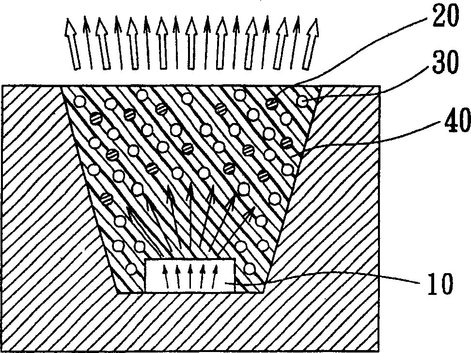
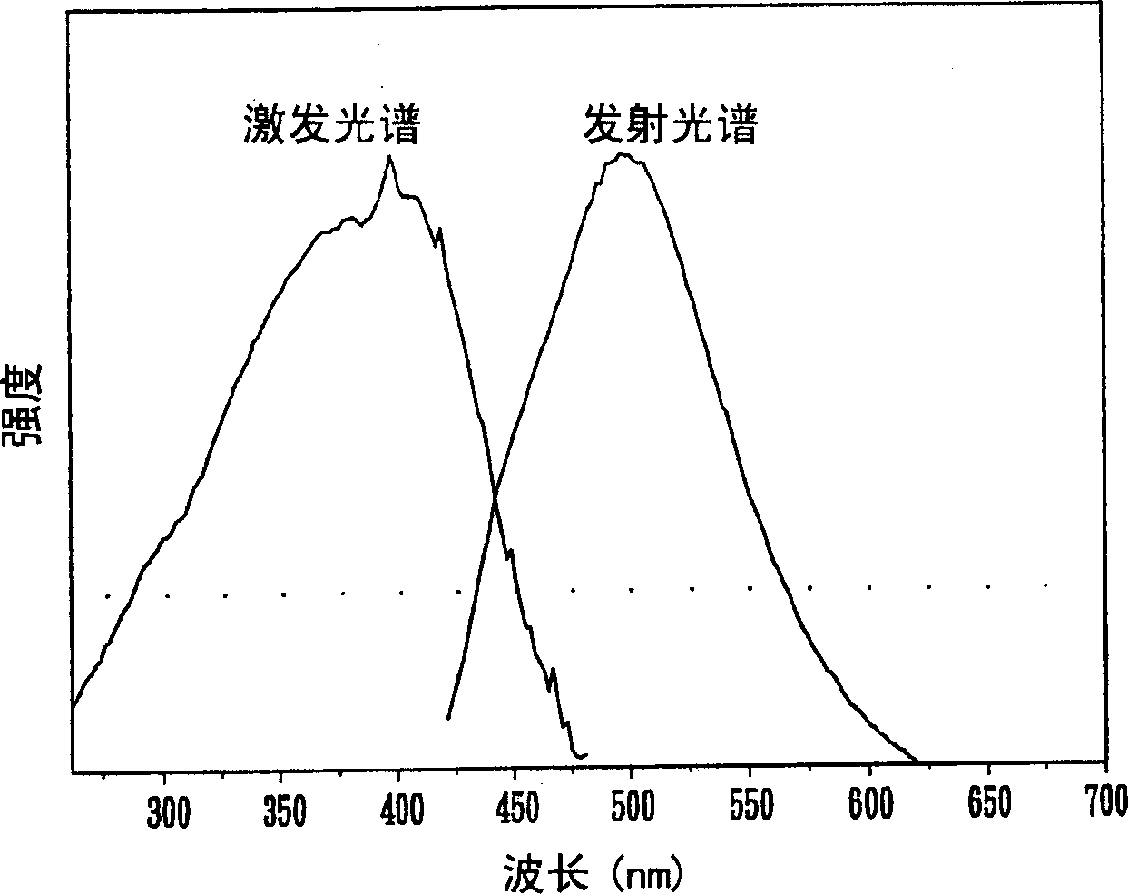
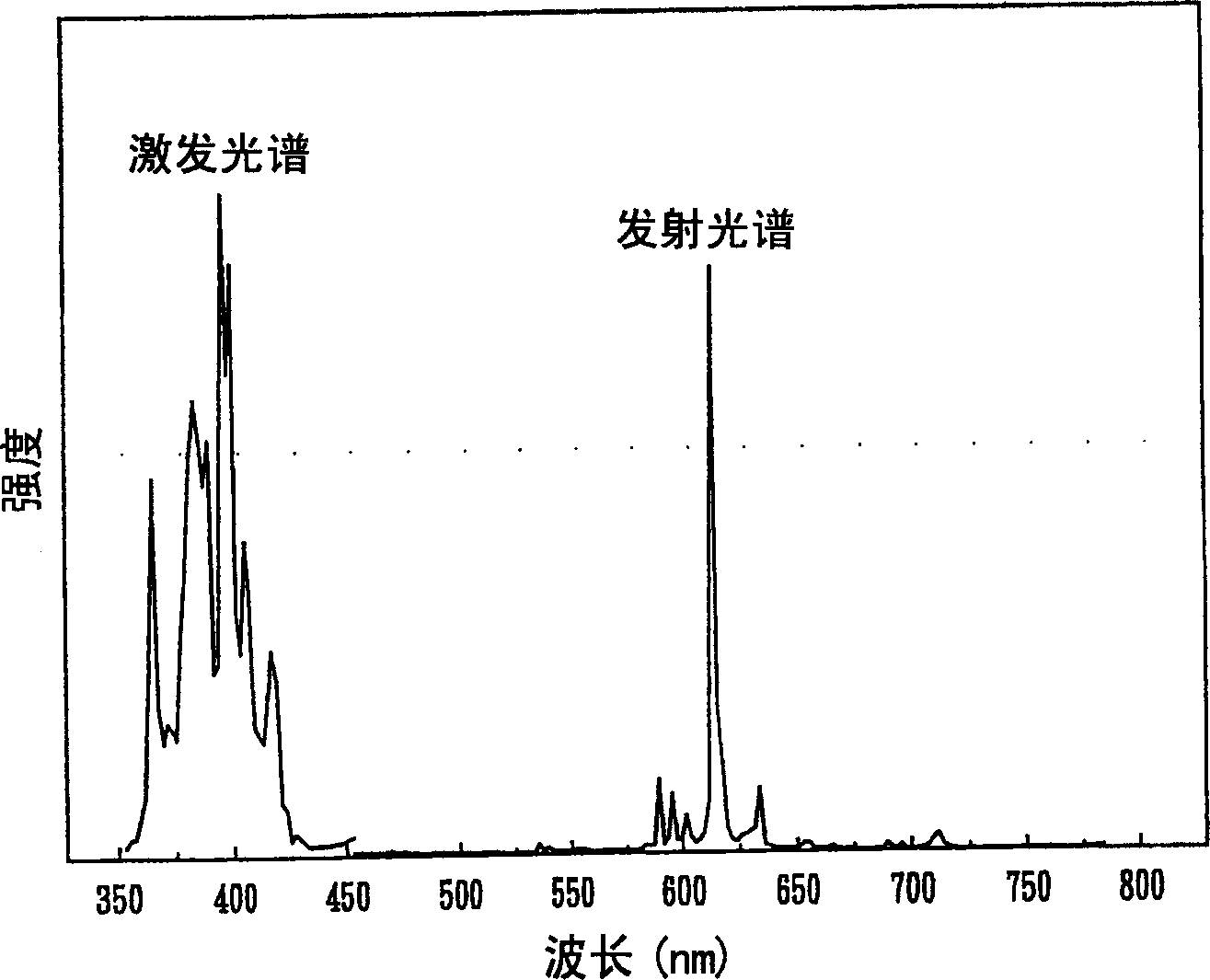
[0033] see figure 1 As shown, the present invention is a white light emitting device, which includes a semiconductor light emitting chip 10, at least one (Ba 1-x m x )Al 2 o 4 Photoluminescent phosphor 20, wherein the M is one element of Eu, Bi, Mn, Ce, Tb, Gd, La, Mg and Sr, and 1>x>0, and at least one (Y 2-x R x )O 3 Photoluminescent phosphor 30, wherein R can be at least one element among Eu, Bi and Gd, 01-x m x )Al 2 o 4 Photoluminescent phosphor 20 and the at least one (Y 2-x R x )O 3 The photoluminescence phosphor 30 absorbs the light emitted by the semiconductor light emitting chip 10 and is respectively excited to emit blue-green light and red light, and the blue-green light is mixed with the red light to obtain white light.

[0034] Wherein the light emitted by the semiconductor light-emitting chip 10 is ultraviolet light, and the wavelength main peak of the ultraviolet light is 350-480nm, which is suppressed by at least one (Ba 1-x m x ) Al 2 o 4 Photo...


PUM


Abstract

This invention relates to a white light emitting device including a semiconductor emitting chip, a blue-green photoluminescence phosphor and a red photoluminescence phosphor, the two phosphors absorb light emitted by the light emitting semiconductor chip to excite blue-green and red light to be mixed to get the white light.

Description

technical field [0001] The invention relates to a white light emitting device, in particular to a white light emitting device in which two kinds of photoluminescent phosphors absorb light from a semiconductor light emitting chip and excite the light, which are mixed with each other to form white light. Background technique [0002] White light is a multi-color mixed light that can be perceived as white light by the human eye, including at least two or more wavelengths. For example, when the human eye is stimulated by red, blue, and green light at the same time, or when it is stimulated by blue light and yellow light at the same time, it can feel white light. Therefore, LED light sources that emit white light can be produced based on this principle. There are four common manufacturing methods for white light LEDs: the first method is to use three LEDs made of InGaAlP, GaN and GaN, and control the current passing through the LEDs to emit red, green and blue light respectively....

Claims


Application Information

Patent Timeline
IPC IPC(8): H01L33/00C09K11/08H01L33/50
CPCY02B20/181Y02B20/00
Inventor 林益山刘如熹苏宏元
Owner LITE ON OPTO TECH (CHANGZHOU) CO LTD
Learn More