Method and device for injection molding
A technology of injection molding and equipment, applied in the direction of coating, etc., can solve the problem of time-consuming partition 510, and achieve the effect of improving productivity
- Summary
- Abstract
- Description
- Claims
- Application Information
AI Technical Summary
Problems solved by technology
Method used
Image

Examples
Example
[0154] Second embodiment
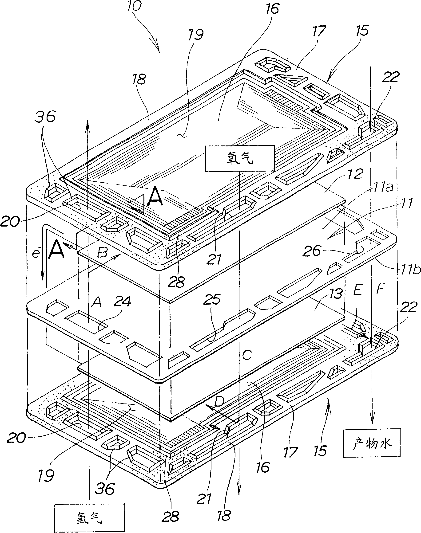
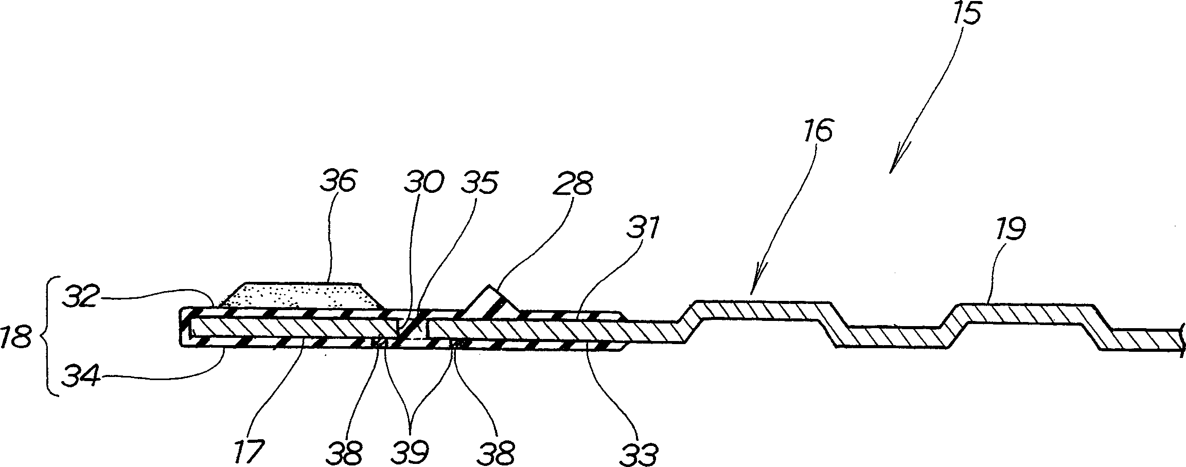
[0155] Such as Picture 9 As shown, the separator 115 is manufactured by covering the circumferential portion 117 of the separator body 116 with a seal 118 made of silicone rubber.
[0156] The partition 115 of the second embodiment is figure 2 The separator 15 of the first embodiment shown has the through hole 30 in the circumferential portion 17 removed, except that its structure is the same as that of the separator 15 of the first embodiment.
[0157] By molding the front side molding layer (the front side area of the sealing member 118) 132 onto the front surface 131 of the partition body 116, and molding the rear side molding layer (the rear side area of the sealing member 118) 134 to the partition On the rear surface 133 of the plate body 116, a seal 118 is formed at the circumferential portion 117 of the partition body 116.
[0158] The circumferential portion 117 is covered by the sealing member 118, and the edges of the hydrogen channel, th...
Example
[0217] The third embodiment
[0218]As shown in FIG. 13, the injection molding equipment 200 has: a first mold 201 that can move up and down as shown by the arrow; a second mold 202 that is arranged under the first mold 201 and can be clamped onto the first mold 201; injection A device 205 connected to the first gate 203 in the first mold 201 and the second gate 204 in the second mold 202; and a control device 206 for opening and closing the first and second gates 203, 204 .
[0219] The first mold 201 has a front cavity surface 150 on its side facing the second mold 202. When the first mold 201 and the second mold 202 are clamped together and the partition body 116 is clamped between the first mold 201 and the second mold 202, the front cavity surface 150 and the front face 131 of the partition body 116 form a front Side cavity 151 (see Figure 14B ).
[0220] In addition, the first mold 201 has a first gate 203 opening at the front cavity surface 150 and a first pressure sensor ...
Example
[0271] Fourth embodiment
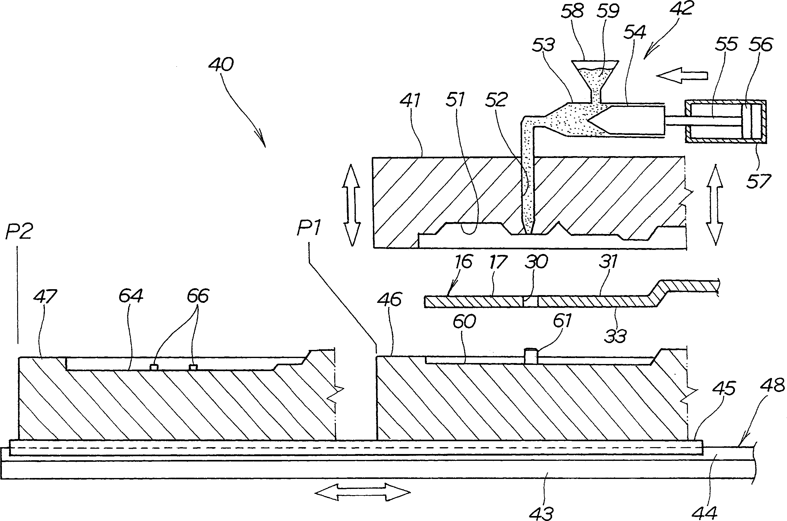
[0272] Such as Figure 18 As shown, the injection molding equipment 340 is composed of a first mold 341, an injection device 342, a base frame 343, a movement device 348, and a second and third molds 346, 347. The first mold 341 is set to rise as shown by the arrow. When descending, the injection device 342 is set on the first mold 341, the bottom frame 343 is set below the first mold 341, the movement device 348 is used to make the slider 345 slide along the guide rail 344 of the bottom frame 343, and the second and The third molds 346 and 347 are mounted on the sliding member 345.
[0273] The moving device 348 is composed of a guide rail 344 provided on the base frame 343, a sliding member 345, and an actuating member (not shown) such as an air cylinder. The sliding member 345 is installed to slide along the guide rail 344 in the direction indicated by the arrow. , And the actuating member is used to make the sliding member 345 slide along the guide r...
PUM
 Abstract
Description
Claims
Application Information
 - R&D Engineer
- R&D Manager
- IP Professional
- Industry Leading Data Capabilities
- Powerful AI technology
- Patent DNA Extraction
Browse by: Latest US Patents, China's latest patents, Technical Efficacy Thesaurus, Application Domain, Technology Topic.
© 2024 PatSnap. All rights reserved.Legal|Privacy policy|Modern Slavery Act Transparency Statement|Sitemap