Split weld cage nut assembly
A technology for locking nuts and assemblies, applied in the direction of locking fasteners, connecting components, threaded fasteners, etc., can solve problems such as hindering the assembly of nuts and bolts
Inactive Publication Date: 2010-12-01
ACUMENT INTPROP LLC
View PDF0 Cites 0 Cited by
- Summary
- Abstract
- Description
- Claims
- Application Information
AI Technical Summary
Problems solved by technology
If a sufficiently thick material is not used, during torque transfer the nut will squeeze out of the outer wall of the housing (thereby causing the seam to widen) until the nut can rotate freely, preventing nut-bolt assembly
Method used
View moreImage
Smart ImageViewing Examples
Examples
Embodiment Construction
Login to View More PUM
 Abstract
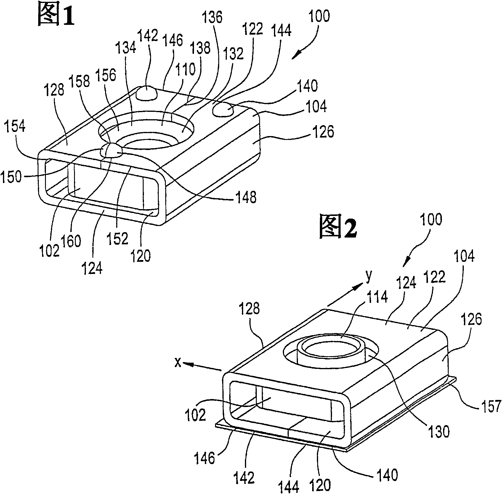
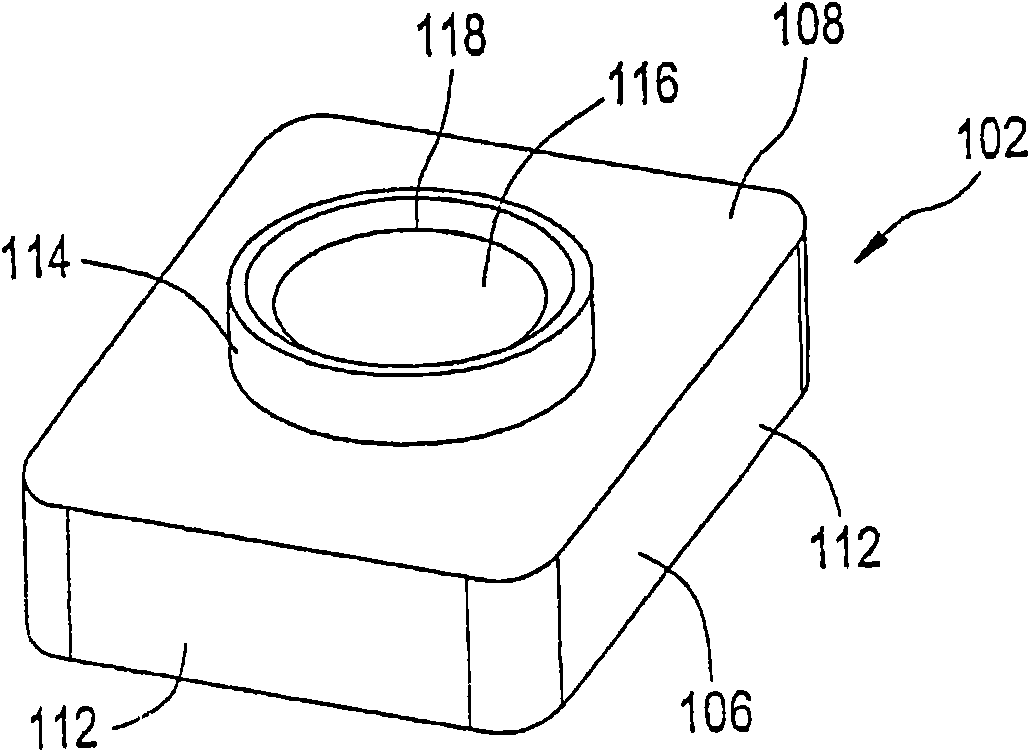
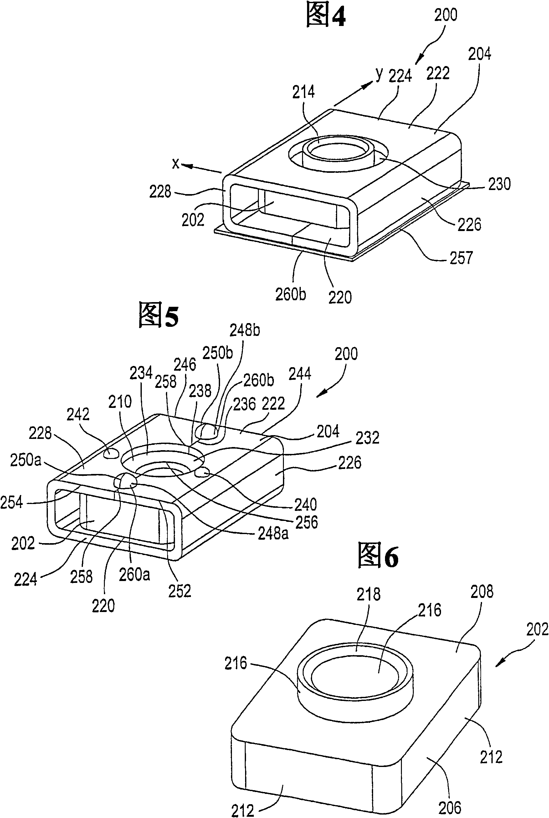
The present invention provides a cage nut assembly 100, 200, 300, 400, 500, 600, 700 having a nut member 102, 202, 302, 402, 502, 602, 702 and a cage member 104, 204, 304, 404, 504, 604, 704. The nut has a threaded aperture 116, 216, 316, 416, 516, 716, therethrough. The cage 104, 204, 304, 404, 504, 604, 704 is capable of encaging the nut 102, 202, 302, 402, 502, 602, 702 such that the nut 102, 202, 302, 402, 502, 602, 702 has a limited range of movement within the cage 104, 204, 304, 404, 504, 604, 704 in at least one dimension. The cage 104, 204, 304, 404, 504, 604, 704 has an aperture 130, 230, 330, 430, 530, 630, 730 therein sized and located to allow access to the threaded aperture 116, 216, 316, 416, 516, 616, 716 of the nut 102, 202, 302, 402, 502, 602, 702 within the range of movement of the nut 102, 202, 302, 402, 502, 602, 702. The cage 104, 204, 304, 404, 504, 604, 704 has a plurality of protrusions 140, 142, 160, 240, 242, 260a, 260b, 340, 342, 360, 440, 442, 460, 540, 542, 560, 64, 642, 699, 740, 742, 760 such as dimples or tabs, extending therefrom. The protrusions 140, 142, 160, 240, 242, 260a, 260b, 340, 342, 360, 440, 442, 460, 540, 542, 560, 640, 642, 699, 740, 742, 760 are capable of being welded to a mating surface to secure the cage 104, 204, 304, 404, 504, 604, 704 to a mating surface. The cage 104, 204, 304, 404, 504, 604, 704 includes a seam 158, 258, 358, 458, 575, 675, 775.
Description
Cage Nut Assemblies for Butt Welds technical field The present invention relates generally to a cage nut assembly, and more particularly to a cage nut assembly configured to meet torque requirements while having a relatively thin wall thickness. Background technique Cage nut assemblies are well known in the art and serve a useful function in that they can hold nuts in locations in the rack that are difficult or sometimes impossible to access. Use cage nut assemblies in vehicles for seat connections, radiator connections, chassis to driveline connections, and any other nut application that requires "X" and "Y" axis adjustability of the nut. Currently, the thickness of the housings in these cage nut assemblies is determined by the amount of torque the parts can take because the housings are not a 360 degree continuous connection, which means there is a seam / gap in the housing. Therefore, in order to prevent the gap from expanding, the housing must have a material thickness...
Claims
Login to View More Application Information
Patent Timeline
 Patent Type & Authority Patents(China)
IPC IPC(8): F16B37/08F16B39/26F16B11/00F16B5/08F16B37/04F16B37/06
CPCF16B37/061F16B37/044F16B5/08
Inventor 詹姆斯·P·克林奇加里·普泽拉
Owner ACUMENT INTPROP LLC
Features
- R&D
- Intellectual Property
- Life Sciences
- Materials
- Tech Scout
- Unparalleled Data Quality
- Higher Quality Content
- 60% Fewer Hallucinations
Learn More Browse by: Latest US Patents, China's latest patents, Technical Efficacy Thesaurus, Application Domain, Technology Topic, Popular Technical Reports.
© 2025 PatSnap. All rights reserved.Legal|Privacy policy|Modern Slavery Act Transparency Statement|Sitemap|About US| Contact US: help@patsnap.com


