
Antenna system and method for measuring the azimuth and elevation angles of an active, signal sending radiosonde

A radiosonde and antenna system technology, which is applied in the field of antenna structure and atmospheric detection system, can solve problems such as inadequacy, ground reflection attenuation, complexity, etc., and achieve the effect of increased reliability and reduced moving parts

Inactive Publication Date: 2006-01-25
VAISALA
View PDF0 Cites 5 Cited by
  • Summary
  • Abstract
  • Description
  • Claims
  • Application Information

AI Technical Summary

Problems solved by technology

The disadvantage of this method is the complex and expensive mechanical receiving antenna structure
[0009] Another disadvantage of existing solutions is the inability to sufficiently attenuate ground reflections when receiving radiosonde signals from low elevation angles

Method used


Image

  • Antenna system and method for measuring the azimuth and elevation angles of an active, signal sending radiosonde
  • Antenna system and method for measuring the azimuth and elevation angles of an active, signal sending radiosonde
  • Antenna system and method for measuring the azimuth and elevation angles of an active, signal sending radiosonde

Examples


Embodiment Construction

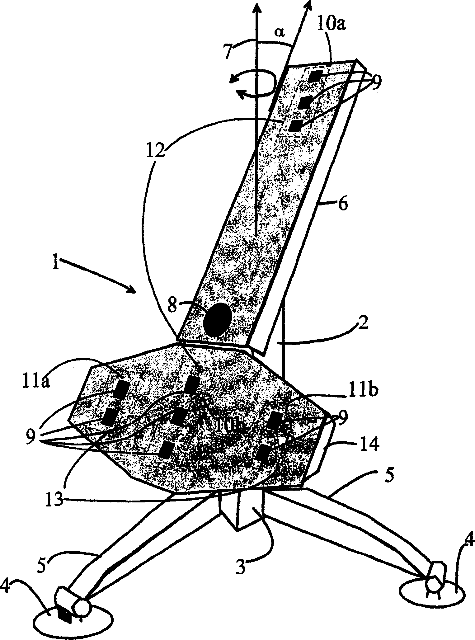
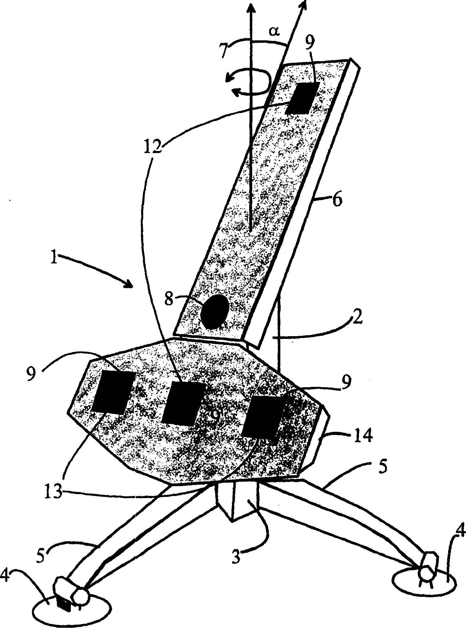
[0025] The substantially planar antenna field 1 according to FIG. 1 comprises a vertical antenna group 12 and a horizontal antenna group 13 . The vertical antenna group 12 comprises at least two antenna arrays 10a and 10b arranged above each other. In this solution each array column comprises three antenna elements 9 . The direction pattern of these arrays 10a and 10b is broad in the elevation plane.

[0026] The vertical antenna groups 10a and 10b are used to determine the elevation angle of the radiosonde from the phase difference of the radiosonde signals received between the antenna arrays 10a, 10b.

[0027] Each horizontal antenna group 13 comprises two horizontal antenna arrays 11 a and 11 b arranged at least substantially symmetrically around the longitudinal centerline of the antenna field 1 . In this solution each array comprises two or more antenna elements 9 . The directional patterns of these arrays 11a and 11b are also broad in the elevation plane.

[0028] Th...


PUM


Abstract

The present invention relates to an antenna system and method. The antenna system for measuring azimuth and elevation angles of an active, signal sending radiosonde (31), comprises a first passive antenna group (13) comprising at least two antenna arrays (11a, 11b), the direction pattern of which is wide at least in elevation plane for measuring azimuth angle of the radiosonde (31) based on the phase differences between the antenna arrays (11a, 11b), a second passive antenna group (12) comprising at least two antenna arrays (10a, 10b), the direction pattern of which is wide at least in elevation plane for measuring the elevation angle of the radiosonde (31) based on the phase differences between the antenna arrays (10a, 10b) and the rotational position of the antenna field (1), and at least one third antenna (8) having high gain for receiving the telemetry signal, the direction pattern of which element (8) is narrow in azimuth plane and wide in elevation plane. According to the invention first (13) and second (12) antenna groups form a solid antenna field (1), and antenna field (1) is fixedly tilted in a predetermined elevation position.

Description

technical field [0001] The invention relates to an antenna structure according to the preamble of claim 1 . [0002] The invention also relates to a method according to the preamble of claim 12 . [0003] The invention also relates to a method for measuring the azimuth and elevation of an active signal transmitting radiosonde. [0004] The present invention relates to an atmospheric sounding system in which the properties of the atmosphere are measured on-site by means of independent self-powered active components, commonly called radiosondes comprising radio transmitters. A typical feature of this solution is the passive (non-transmitting) reception of the antenna and the fact that the measuring device (radiosonde) is lifted or dropped through the space to be measured. Background technique [0005] Parameters such as air pressure, temperature and relative humidity measured in situ by the sensors of the radiosonde are transmitted via a telemetry device connected to the rec...

Claims


Application Information

Patent Timeline
Patent Type & Authority Applications(China)
IPC IPC(8): H01Q3/04H01Q21/29G01S3/46G01S3/04H01Q3/24H01Q21/28
CPCH01Q21/28H01Q3/04G01S3/04G01S3/46H01Q3/242G01S3/48
Inventor H·安德森P·卡胡宁J·科尔特J·亚蒂宁
Owner VAISALA
Learn More