
Ventilation system integrated with air cleaning equipment

An air purification device and ventilation system technology, applied in the field of ventilation systems, can solve the problems of increasing costs and occupying indoor space

Inactive Publication Date: 2006-02-01
LG ELECTRONICS (TIANJIN) APPLIANCES CO LTD
View PDF0 Cites 6 Cited by
  • Summary
  • Abstract
  • Description
  • Claims
  • Application Information

AI Technical Summary

Problems solved by technology

[0022] When the air purification device is installed separately, it not only takes up indoor space, but also increases the cost for its installation.

Method used


Image

  • Ventilation system integrated with air cleaning equipment
  • Ventilation system integrated with air cleaning equipment
  • Ventilation system integrated with air cleaning equipment

Examples


Embodiment Construction

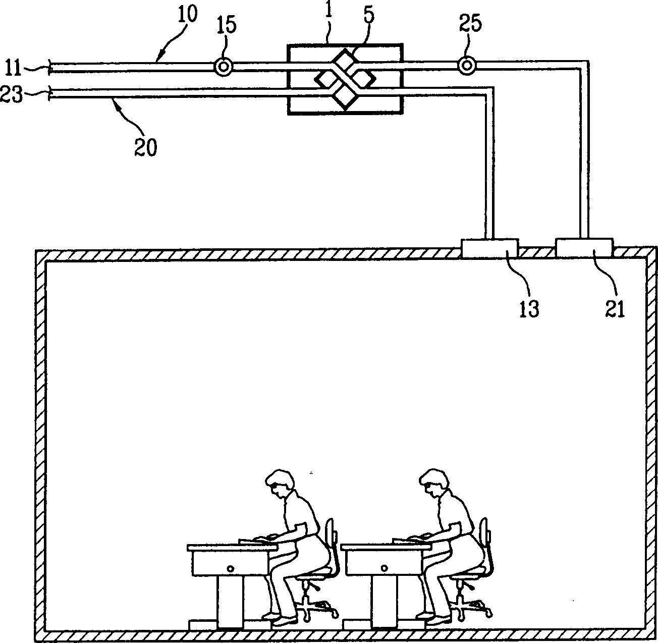
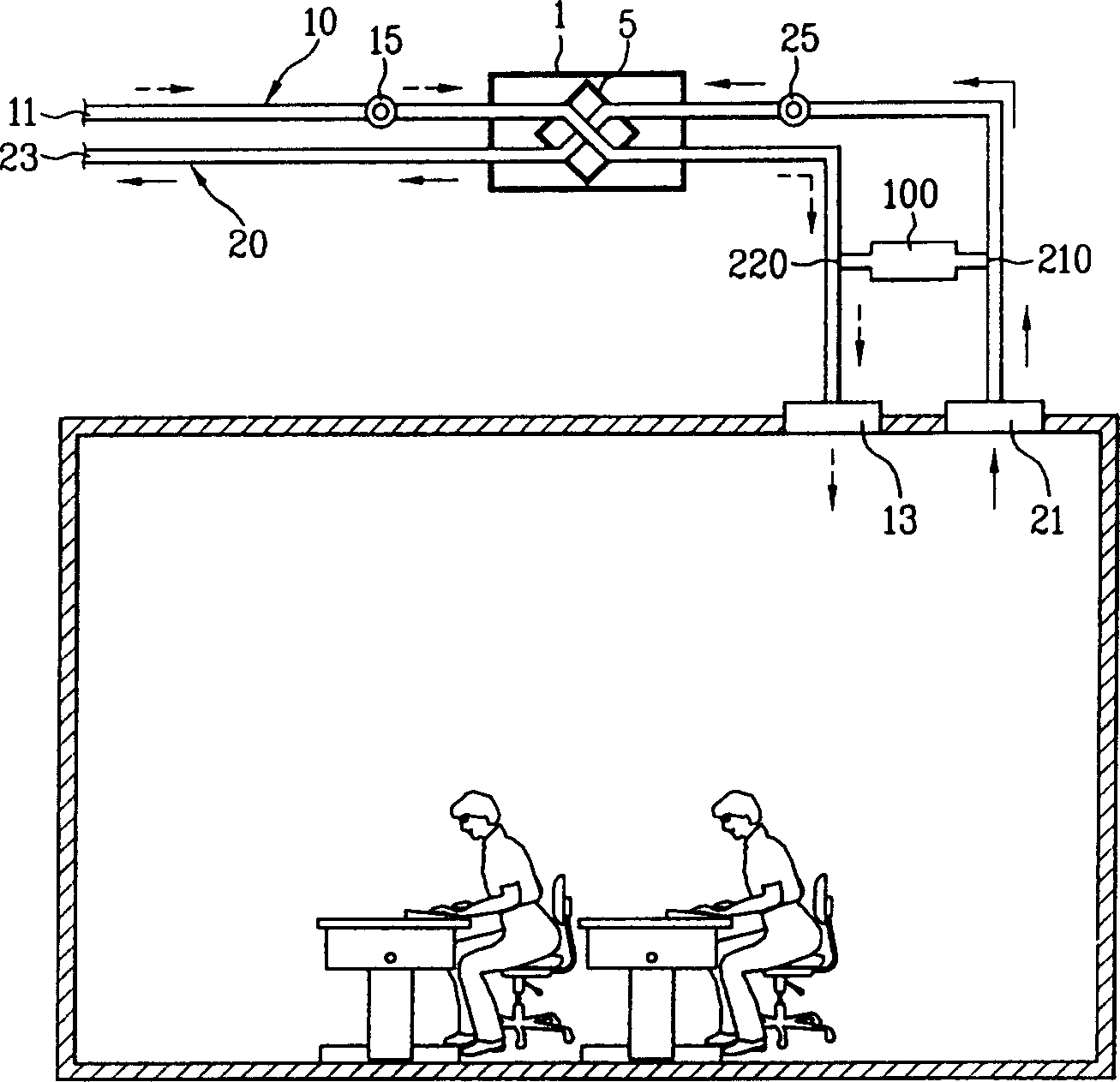
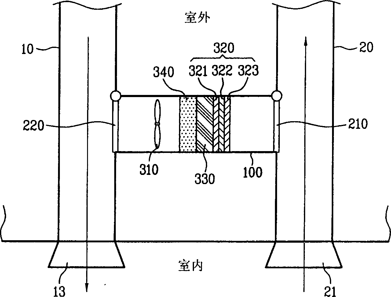
[0049] Below, refer to Figure 2 to Figure 7 The present invention will be described in detail.

[0050] In the following description, in order to avoid duplication of description, the same structures as those in the conventional art refer to the original symbols.

[0051] figure 2 It is a schematic diagram of the structure of an embodiment of the ventilation system of the present invention with an air purification device when performing total heat ventilation. image 3 It is a schematic diagram of the air flow state when the total heat exchange ventilation is performed in an embodiment of the present invention.

[0052] Figure 4 It is a schematic diagram of the structure when performing air-purifying ventilation in an embodiment of the ventilation system of the present invention with an air-purifying device. Figure 5 In one embodiment of the present invention, it is a schematic diagram of the circulation state of indoor polluted air during air purification ventilation....


PUM


Abstract

The present invention provides air purification equipment. It includes the following portions: air supply pipeline, exhaust pipeline, air supply fan, and exhaust fan, full heat exchanger, circulating pipeline, opening / closing device and air purification device. Said invention also provides the concrete function of the above-mentioned every component and their connection mode.

Description

technical field [0001] The present invention relates to a ventilation system (air cleaning system with ventilator); more specifically, the present invention relates to a ventilation system integrated with an air purification device, which supplies fresh air to the room by treating outdoor air or indoor polluted air . Background technique [0002] The air in a closed space, due to the respiration of living organisms, will increase the concentration of carbon dioxide as time goes by, which will hinder the respiration of living organisms. Therefore, when many people gather in a small space such as an office or a vehicle, it is necessary to ventilate the indoor space at any time. At this time, a ventilation system is usually used. [0003] Most of the existing ventilation systems usually adopt the method of forcibly discharging the indoor air to the outside by utilizing a blower fan. However, when only the indoor air is discharged to the outside through a blower, the cold or ...

Claims


Application Information

Patent Timeline
Patent Type & Authority Applications(China)
IPC IPC(8): F24F7/08F24F13/10B01D61/14
Inventor 金暻桓李周妍金廷勇
Owner LG ELECTRONICS (TIANJIN) APPLIANCES CO LTD
Learn More