Punching-pressing composite mould

A stamping die and die base technology, applied in the field of composite die structure, can solve the problems of inability to produce high-precision stamping parts, low efficiency, and precision that cannot meet the requirements, and achieve the effect of simple structure

Inactive Publication Date: 2006-02-15
LANZHOU UNIVERSITY OF TECHNOLOGY
View PDF0 Cites 23 Cited by
  • Summary
  • Abstract
  • Description
  • Claims
  • Application Information

AI Technical Summary

Problems solved by technology

[0005] Through analysis, scheme (1) has a simple mold structure, but requires 3 sets of molds, which is very inefficient and cannot produce high-precision stamping parts; scheme (2) has a slightly more complicated structur...

Method used


Image

  • Punching-pressing composite mould

Examples


Embodiment Construction

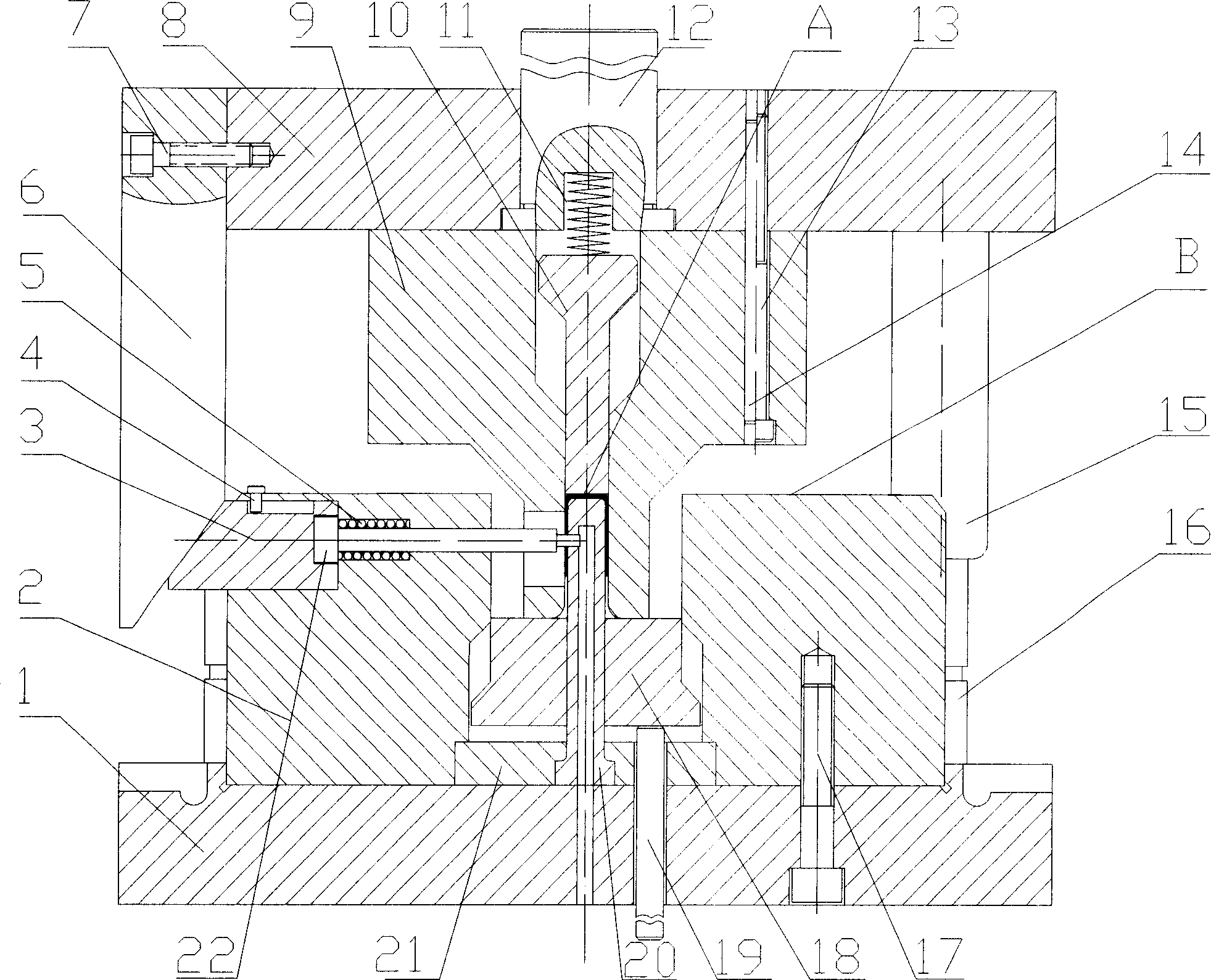
[0013] Such as Figure 1 As shown, the composite stamping die of the present invention includes two parts, a lower die and an upper die. The lower mold consists of the lower mold base (1), the positioning block (2) installed on the lower mold base (1) through the positioning holes and screws (17) on the lower mold base (1), and the positioning installation of the positioning block (2). The punch fixed plate (21) on the lower mold base (1) central position, the bending punch (20) installed on the lower mold base (1) central position by the punch fixed plate (21), the bending punch (20) installed on the curved punch ( 20) around the lower ejector (18), the drag bar (19) and guide post (16) directly installed on the lower mold base (1), and the side sliding post (3) directly installed in the positioning block (2), Composed of a horizontal punch (22), a return spring (7), and a limit pin (6), the upper end surface (A) of the bending punch (20) is about 2-3 lower than the upper en...


PUM


Abstract

This complex press mould comprises upper and lower moulds. Wherein, the lower mould comprises base with arranged locating block, dead plate for convex mould on base center by block with bending convex mould of top end surface lower 2~3 blank thickness than the locating block 's, lower backing-out punch on edge of bending convex mould, towbar and guide pole both arranged directly on base, and sideslip pole, horizontal press head, reset spring and limiting pin all arranged in locating block; the upper mould comprises base with shank on base center by locating hole, swaging spring on shank, bending concave mould below base center with swaging block, wedge and guide sleeve both arranged on base side by bolt and locating plot; wherein, the upper is matched with lower mould by guide sleeve and guide pole.

Description

technical field [0001] The invention relates to a stamping die, in particular to a composite die structure of several stamping processes. Background technique [0002] At present, the basic stamping process for the forming of side arm with small hole bending is: blanking, bending, punching. There are two specific forming process schemes as follows: [0003] (1) Blanking, bending, punching single-process mold forming; [0004] (2) Blanking and punching are compounded first, and the bending single-process mold is formed; [0005] Through analysis, scheme (1) has a simple mold structure, but requires 3 sets of molds, which is very inefficient and cannot produce high-precision stamping parts; scheme (2) has a slightly more complicated structure and requires 2 sets of molds, which improves efficiency and accuracy Still can't meet the requirement. These two schemes are far from meeting the requirements of modern production with high precision, low cost and high benefit. Conte...

Claims


Application Information

Patent Timeline
IPC IPC(8): B21D37/10
Inventor 聂福荣
Owner LANZHOU UNIVERSITY OF TECHNOLOGY
Why Eureka
Try Eureka