

Spindle motor, disc driving apparatus having the same, and production method thereof
A disk drive device, spindle motor technology, applied in the direction of electromechanical devices, electric components, bearings, etc., can solve the problems of increasing production costs, increasing the number of screw-in parts, increasing the number of parts, etc., to eliminate strain and deflection, and suppress hub deformation , Realize the effect of miniaturization and thinning
- Summary
- Abstract
- Description
- Claims
- Application Information
AI Technical Summary
Problems solved by technology
Method used
Image

Examples
Embodiment approach 1
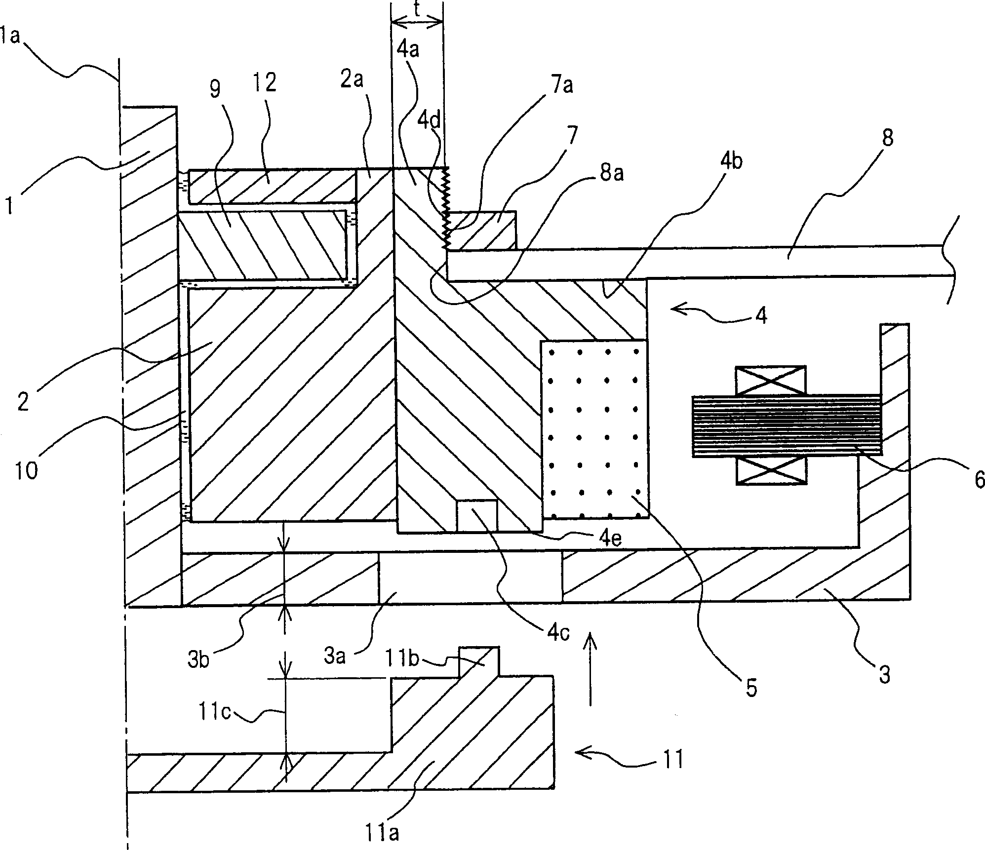
[0049] use figure 1 , the spindle motor according to Embodiment 1 of the present invention will be described. figure 1 It is a cross-sectional view showing the right half of the disk drive device having the spindle motor according to Embodiment 1. The left side from the central axis (axis 1a) has the same configuration as the above-mentioned right half, and thus is omitted from illustration.
[0050] figure 1 Among them, the lower end of the shaft 1 is fixed on the base 3 . Fixing of axis 1 to base 3, such as figure 1 As shown, it can be carried out by pressing, bonding, welding, and combinations thereof. Additionally, if Figure 4 As shown, it can also be done with fastening screws. A disk-shaped thrust flange 9 is fixed or integrally processed on the outer peripheral surface of the shaft 1 . The structure of the bearing is, for example, as follows. The bushing 2 has a cylindrical portion 2a, and an annular thrust plate 12 is press-fitted or adhered to the inner pe...
Embodiment approach 2
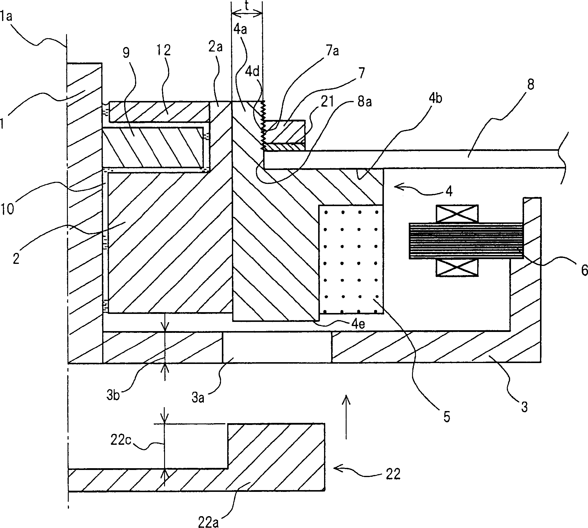
[0064] use figure 2 , the spindle motor according to Embodiment 2 of the present invention will be described. figure 2 It is a cross-sectional view showing the right half of the disk drive device having the spindle motor according to Embodiment 2. The left side from the central axis (axis 1a) has the same configuration as the above-mentioned right half, so illustration is omitted.
[0065] figure 2 , without setting figure 1 Embodiment 1 shown above differs from Embodiment 1 in that positioning holes 4c are provided, that spring member 21 is provided between the lower surface of clamper 7 and the upper surface of disk 8 , and that bearing jig 22 is provided instead of positioning jig 11 . In other respects, it has the same configuration, and thus redundant description is omitted.
[0066] The spring member 21 is an annular elastic member made of a rubber material or the like, and is provided to protect the surface of the disk 8 from the clamper 7 in addition to absorbin...
Embodiment approach 3
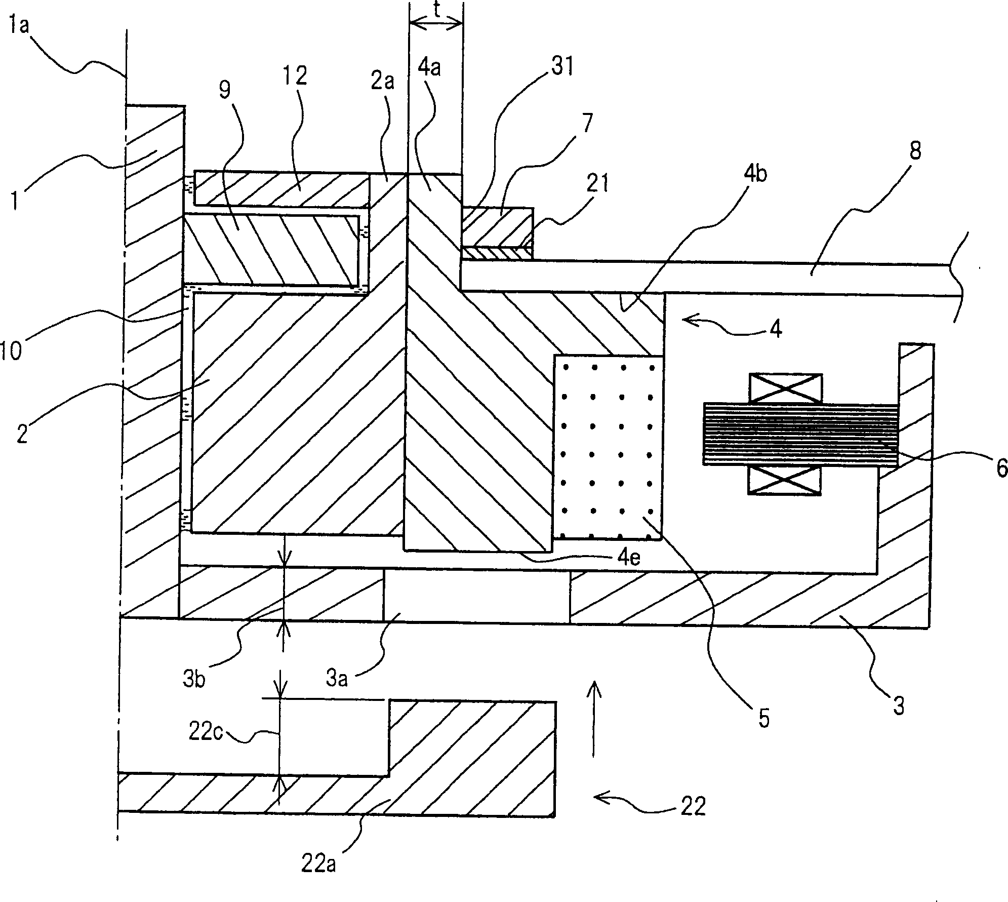
[0073] use image 3 , the spindle motor according to Embodiment 3 of the present invention will be described. image 3 It is a cross-sectional view showing the right half of the disk drive device including the spindle motor according to Embodiment 3, and the left side from the center axis (axis 1a) has the same configuration as the above-mentioned right half, so illustration is omitted.
[0074] image 3 in, replace figure 2 The male thread 4d of the hub 4 and the female thread 7a of the clamper 7 shown in the above-mentioned second embodiment have a shrink fit portion 31 . In other respects, it has the same configuration, and thus redundant description is omitted.
[0075] The shrink-fit portion 31 is formed by heating and expanding the clamper 7 to expand its diameter, fitting it into the outer peripheral surface of the cylindrical portion 4a in this state, cooling it, and fixing the clamper 7 to the cylindrical portion 4a.
[0076] The manufacturing process of the disk...
PUM
| Property | Measurement | Unit |
|---|---|---|
| diameter | aaaaa | aaaaa |
Abstract
Description
Claims
Application Information