

Method for increasing CCD image collection system frame rate
A technology of image acquisition and system frame, which is applied in the parts of TV system, scanning details of TV system, image communication, etc. It can solve the problems of reduced tracking accuracy, inability to track fast-moving targets, and target loss, etc.
- Summary
- Abstract
- Description
- Claims
- Application Information
AI Technical Summary
Problems solved by technology
Method used
Image

Examples
Embodiment 1-T
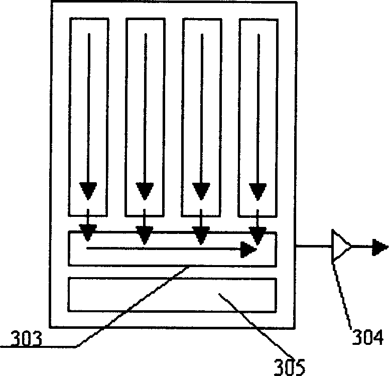
[0075] Embodiment 1-TC237B frame transfer CCD
[0076] see first Figure 4 with Image 6 , Figure 4 It is the structure diagram of TC237B CCD, Image 6 It is a schematic diagram of the position of the sub-window in the present invention.
[0077] Before introducing the specific implementation of the "sub-window working mode", let me explain some terms used in the present invention:
[0078] The "position" is the coordinates of the sub-window 1109 relative to the reference point on the photosensitive surface of the CCD. For example, take the pixel at the lower left corner of the imaging area 11 as the reference point, that is, the coordinate origin 1108 . The point representing the position of the window is the point at the lower left corner of the window, which is called the "head pixel" 115 . In this way, the position of the sub-window 1109 can be represented by the coordinate value of the first pixel 115 of the sub-window relative to the coordinate origin 1108 . Ther...
Embodiment 2
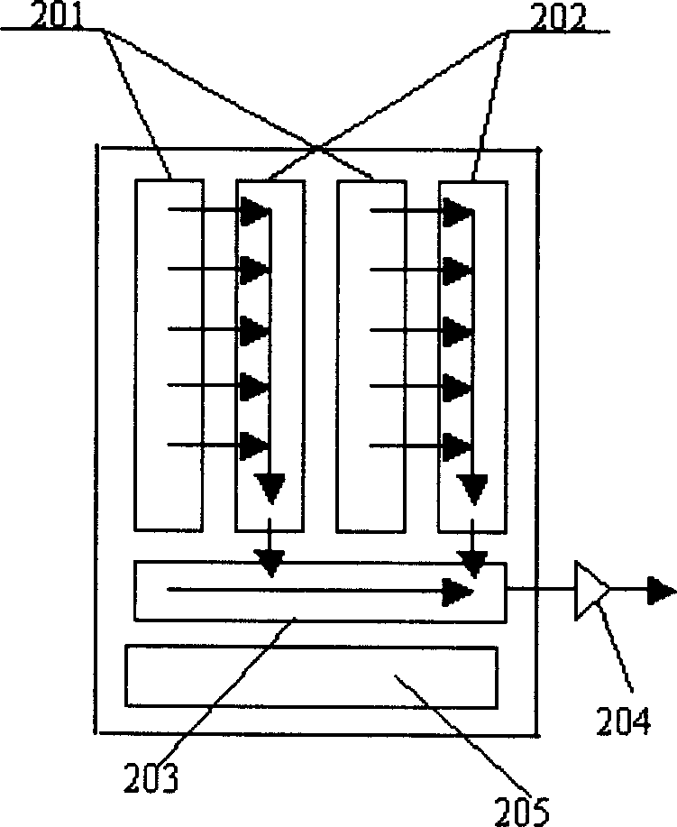
[0095] Example 2 - Alternate Column Transfer CCD
[0096] The present invention improves the method for frame rate of CCD image acquisition system, comprises the following steps for every column transfer type CCD:
[0097] ① The user sets a sub-window whose first pixel coordinates are (i, j) and whose size is m rows×n columns in the imaging bar of M rows×N columns through commands;
[0098] ② The CCD is applied to the CCD by the CCD driver with the following sequence of driving pulses:
[0099] Q 2 → Z 2 →(jX 2 )→m[X 2 →(i+n)D 2 ]→(M-j-m)X 2 , the CCD will output a frame of the image of the sub-window, wherein:
[0100] Q 2 The clearing pulse is a pulse applied to the clearing pin of the alternate column transfer type CCD, so that the CCD imaging strip is cleared. After clearing, the exposure strip of the CCD is automatically exposed to generate charges corresponding to the scene;
[0101] Z 2 It is the frame shifting pulse of the column transfer type CCD, Z 2 A com...
Embodiment 3
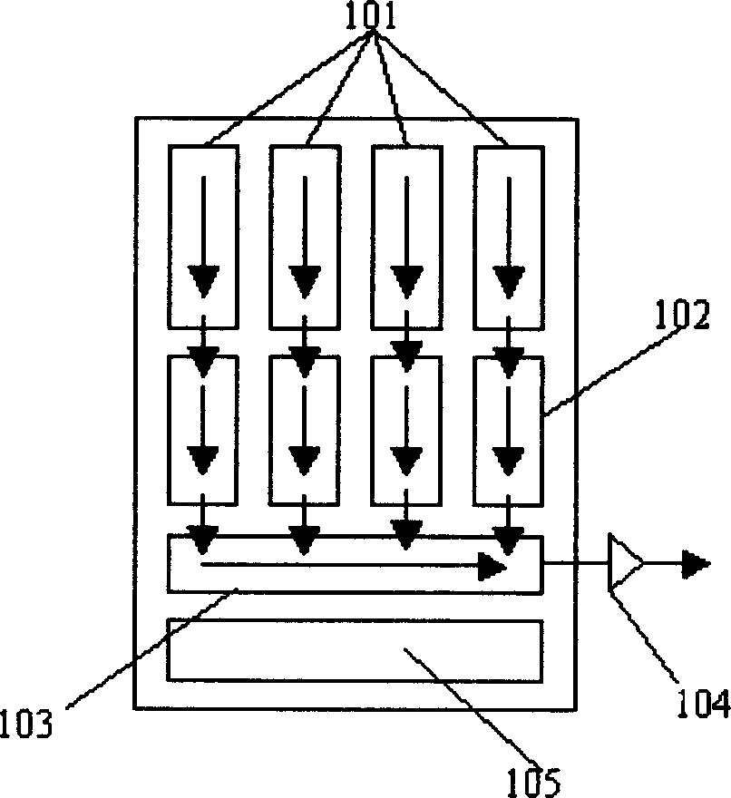
[0105] Embodiment 3-full frame type CCD
[0106] The present invention improves the method for CCD image acquisition system frame rate, comprises the following steps for full-frame type CCD this method:
[0107] ① Set a sub-window whose head pixel coordinates are (i, j) and whose size is m rows×n columns in the imaging area of M rows×N columns by command;
[0108] ② The CCD is applied to the CCD by the CCD driver with the following sequence of driving pulses:
[0109] Q 3 →(jX 3 )→m[X 3 →(i+n)D 3 ], the CCD will output the image of a frame of the sub-window, wherein:
[0110] Q 3 It is a full-frame CCD clearing pulse, so that the CCD imaging area is cleared, the exposure area of the CCD starts to be exposed, and the exposure area generates charges corresponding to the scene;
[0111] x 3 It is a full-frame type CCD line translation pulse, X 3 Represents the combined pulse of an imaging pulse applied to the imaging area pin of the CCD and a serial pulse of the seri...
PUM
 Abstract
Description
Claims
Application Information