Anti-scour and cavitation-resistant high pressure difference regulating valve

A high-pressure differential and regulating valve technology, applied in the field of high-pressure differential regulating valves, can solve problems affecting the service life of high-pressure differential regulating valves, improve the performance of anti-scouring and cavitation resistance, reduce impact and cavitation, and prolong service life Effect

Inactive Publication Date: 2006-03-01
天津市圣恺工业技术发展有限公司
View PDF0 Cites 5 Cited by
  • Summary
  • Abstract
  • Description
  • Claims
  • Application Information

AI Technical Summary

Problems solved by technology

Therefore, the severe erosion and cavitation of the high-pressure steam on the metal sleeve of the high-pressure differential control valve and the metal sealing surface will a

Method used


Image

  • Anti-scour and cavitation-resistant high pressure difference regulating valve

Examples


Embodiment

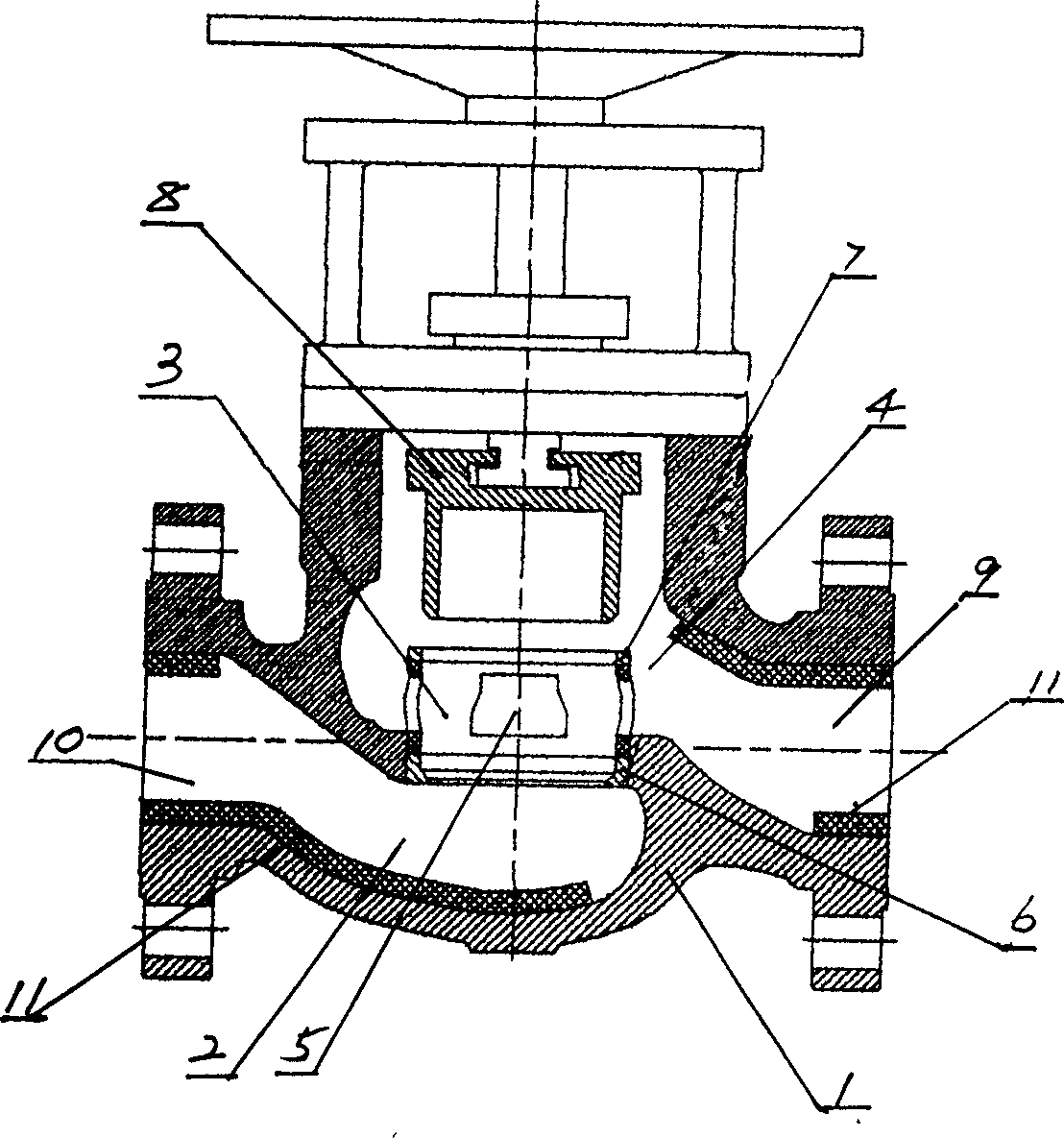
[0019] When the present invention is used in a system with a steam pressure difference of 3.7Mpa between the valve inlet and the outlet;

[0020] The specification of the valve body 1 of the present invention adopts a PN of 64Mpa and a DN of 50mm. Among them, the diameter of the sleeve 3 is 70mm and the height is 40mm; four orifices 5 are evenly arranged on the cylinder wall, and the distance between the orifice 5 and the sealing surface A6 is 3mm; the inlet 10 and the outlet 9 of the valve body 1 are lined with The structural ceramic layer 11 is covered, and the bottom of the inlet channel 2 and the position of the valve body cavity 4 close to the outlet 9 are lined with the structural ceramic layer 11 .

[0021] When the valve plug 8 is inserted into a part of the sleeve 3, the valve plug 8 covers a part of the orifice 5 on the cylinder wall of the sleeve 3, and the high-pressure steam enters the inlet passage 2 through the inlet 10, and passes through the uncovered part of ...


PUM


Abstract

The anti-scour and cavitation-resistant high pressure difference regulating valve is superior to traditional high pressure difference regulating valve and 10-15 times longer service life. It includes valve body, inlet channel connected to the inlet, sleeve with throttle port, inner valve body cavity connected to the outlet, and valve stopper. It features the sleeve of structural ceramic and with two sealing planes including sealing plane A near the inlet channel and sealing plane B over the throttle port; and the inner valve body cavity with structural ceramic lining. The present invention is used in petrochemical, electrical and other industry for pressure difference control in high temperature and high pressure steam pipeline.

Description

[0001] Field of study [0002] The invention relates to a high pressure difference regulating valve. Especially a kind of anti-scouring and anti-cavitation high-pressure differential regulating valve. Background technique [0003] In industrial production such as petrochemical industry or electric power, the transportation of high-temperature and high-pressure steam generated by the boiler needs to be controlled by a regulating valve. Since the steam must be transported with pressure, the pressure will have a scouring effect on the regulating valve, and the scouring force will speed up the adjustment. The valve seat and valve core of the valve are worn; and the regulating valve is working under a high pressure differential state. When the high pressure medium passes through the valve under the high pressure differential state, the huge energy released will produce throttling elements such as the valve seat and valve core of the valve. It is difficult for existing metal materi...

Claims


Application Information

Patent Timeline
IPC IPC(8): F16K3/26F16K3/34
Inventor 王忱
Owner 天津市圣恺工业技术发展有限公司
Why Eureka
Try Eureka