Fluorescent lamp tube and plane lamp

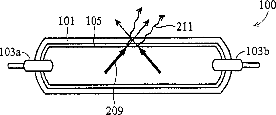
A technology for fluorescent tubes and flat lamps, which is applied to discharge lamps, gas discharge lamps, parts of gas discharge lamps, etc., can solve the problems of inability to effectively utilize ultraviolet light, and the inability of the fluorescent layer 105 to completely absorb ultraviolet light and visible light.

Inactive Publication Date: 2006-03-01
AU OPTRONICS CORP
View PDF0 Cites 17 Cited by
  • Summary
  • Abstract
  • Description
  • Claims
  • Application Information

AI Technical Summary

Problems solved by technology

However, the fluorescent layer 105 cannot completely absorb the ultraviolet light 209 to generate visible light, and part of the ultraviolet light 209 will be absorbed by the cavity wall and conv...

Method used


Image

  • Fluorescent lamp tube and plane lamp
  • Fluorescent lamp tube and plane lamp
  • Fluorescent lamp tube and plane lamp

Examples


Embodiment Construction

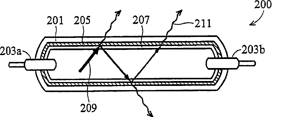
[0013] figure 2 A fluorescent lamp 200 with a dielectric omni-directional reflective layer in a preferred embodiment of the present invention is shown, including a transparent lamp 201, such as a glass lamp, with a pair of electrodes 203a and 203b at both ends of the lamp. In this figure, a cold cathode fluorescent lamp (CCFL) is taken as an example, and the electrodes are located inside the lamp. However, the electrodes can also be placed outside the lamp, eg in the design of an external electrode fluorescent lamp (EEFL). The inner wall of the fluorescent tube has a dielectric omni-directional reflective layer 205 and a fluorescent layer 207, wherein the dielectric omni-directional reflective layer 205 is placed between the transparent lamp tube 201 and the fluorescent layer 207, which is a light in the range of visible light. Periodically stack reflective layers for transparency. The principle of reflection is to use the energy gap phenomenon generated by the periodic str...


PUM


Abstract

A fluorescent lamp tube consists of a transparent lamp tube , a sealed cavity packed with gas , a pair of electrodes being set at two ends of said lamp tube , a dielectric substance fully reflecting layer set on internal wall of said lamp tube for reflecting all ultraviolet ray in sealed cavity , a fluorescent layer set on dielectric substance fully reflecting layer for reacting on with ultraviolet ray to generate visible light and a planar lamp structure with said dielectric substance fully reflecting layer .

Description

technical field [0001] The invention relates to a fluorescent lamp tube and a plane lamp, in particular to a fluorescent lamp tube and a plane lamp with a dielectric omnidirectional reflection layer. Background technique [0002] Because of its high luminous intensity and uniform luminescence, the lamp tube can be made into extremely thin and can be made into various shapes, and can also be made into a flat plate as a flat light source, so it is currently used in liquid crystal displays, scanners, and automotive instruments. It has been widely used in the fields of plate, micro-advertising light box and mirror frame production. Generally speaking, the cold cathode fluorescent lamp is usually used as the backlight of the above products, and it is a novel miniature strong light source. [0003] Conventional CCFL tubes 100 such as figure 1 As shown, there is a layer of fluorescent layer 105 on the inner wall of the transparent lamp tube 101, a pair of electrodes 103a and 103b...

Claims


Application Information

Patent Timeline
IPC IPC(8): H01J61/35H01J61/12H01J65/00H01J61/00
Inventor 许宏彬蓝元柯胡克龙
Owner AU OPTRONICS CORP
Why Eureka
Try Eureka