Delayed controlled stripe-free spectrum phase interference pulse measuring method and its measuring device

A phase interference and pulse technology, applied in the direction of the instrument, can solve the problems of spectrometer resolution, dense interference spectrum fringes, pulse phase reconstruction deviation, etc.

Inactive Publication Date: 2006-03-08
SUN YAT SEN UNIV
View PDF0 Cites 39 Cited by
  • Summary
  • Abstract
  • Description
  • Claims
  • Application Information

AI Technical Summary

Problems solved by technology

In this way, a part of the transient information of Δφ(ω) is easily lost, and a part of D 1 (ω) and D 2 The transient information of (ω) is mixed into the filter window, so that the filter window contains not all and pure Δφ(ω) information, which will lead to obvious deviations in the reconstruction of the pulse phase
[0009] In addition, if a pulse with a larger pulse width is to be measured, a larger dela...

Method used


Image

  • Delayed controlled stripe-free spectrum phase interference pulse measuring method and its measuring device
  • Delayed controlled stripe-free spectrum phase interference pulse measuring method and its measuring device
  • Delayed controlled stripe-free spectrum phase interference pulse measuring method and its measuring device

Examples


Embodiment Construction

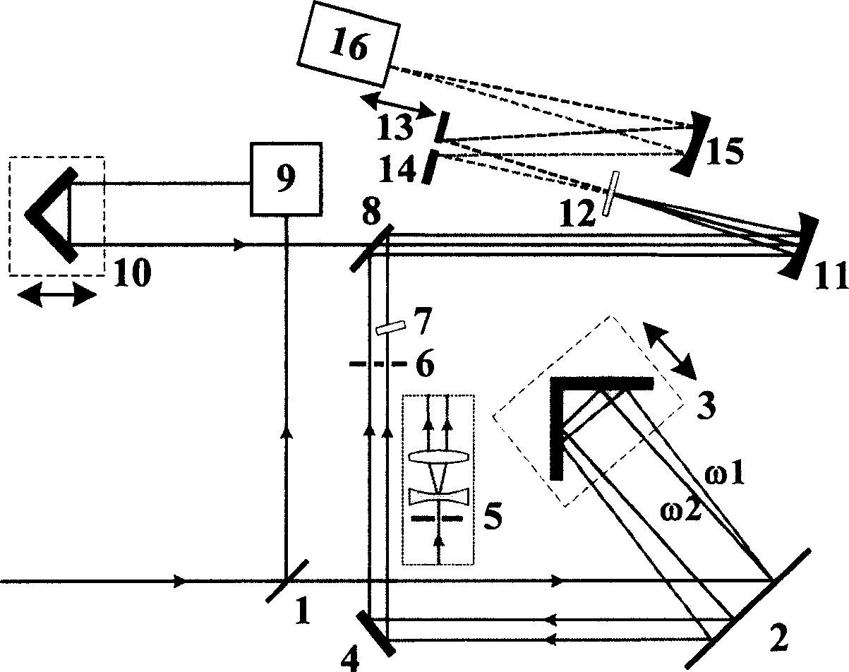
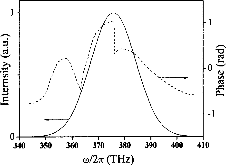
[0053] Assuming that femtosecond pulses generated by pulse shaping techniques are as figure 2 Spectral and phase structures shown. The pulse width is about 60fs, the center frequency ω 0 =2π×375THz (that is, the central wavelength λ 0 =800nm), there is a jump somewhere in its spectral phase curve.

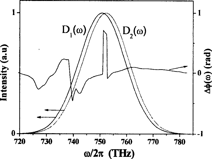
[0054] When the pulse enters figure 1 After the optical system shown, the two circular frequencies selected by the double slit are ω 1 = 2π×375THz and ω 2 =2π×376.5THz (ie Ω=2π×1.5THz) quasi-monochromatic long pulses, they will independently have a sum frequency effect with the same replica pulse in the crystal, thereby generating two sum frequency pulses. For simplicity, assuming that the sum-frequency efficiencies of the different frequency components of the pulses are equal, the spectral intensities D of the two sum-frequency pulses 1 (ω) and D 2 (ω) curve, and the corresponding spectral phase difference Δφ(ω) curve, should be as image 3 shown. By driving one of the m...


PUM


Abstract

This invention refers to a method and device for measuring super short laser pulse, which adopts different optical structure with traditional Spectral Phase Interferometry for Direct Electric-field Reconstruction (SPIDER), sum-frequency of the copy pulse of a pulse to be measured with two quasi-monochrome long pulses with different frequency to generate two frequency spectrum sheared sum-frequency, leading defined small time delay between said two pulses through piezoelectric driven single reflection mirror or step reflection mirror, combined with measured single sum-frequency spectrum to calculate point-to-point spectrum phase difference of pulse to be measured, then reconstructing pulse spectrum phase without using Fourier transformation filter process.

Description

technical field [0001] The invention relates to a measurement method for ultrashort laser pulses, and a measurement device capable of implementing this method. The measurement method is a time-delay controlled fringe-free spectral phase interferometry. technical background [0002] At present, femtosecond laser technology has been greatly developed, and the generation, shaping and application of femtosecond pulses require precise measurement of pulse shape and phase structure. The traditional autocorrelation method can only estimate the width of the pulse, which cannot meet the actual needs. The frequency-resolved optical switching method (FROG) and the spectral phase coherent electric field reconstruction method (SPIDER) have become the standard methods for evaluating femtosecond pulses because they are relatively simple and practical, and can give all the information of the pulse. [0003] Compared with the FROG method, SPIDER needs to collect less data, the inversion al...

Claims


Application Information

Patent Timeline
IPC IPC(8): G01J11/00
Inventor 文锦辉雷亮林位株赖天树
Owner SUN YAT SEN UNIV
Why Eureka
Try Eureka