Ultrasonic detecting device and its detecting method

A detection device, ultrasonic technology, applied to measuring devices, using sound waves/ultrasonic waves/infrasonic waves to analyze solids, and re-radiation of sound waves, etc., to achieve the effect of saving detection time

Inactive Publication Date: 2006-03-08
崔志国
View PDF0 Cites 18 Cited by
  • Summary
  • Abstract
  • Description
  • Claims
  • Application Information

AI Technical Summary

Problems solved by technology

[0004] A new type of ultrasonic detection device and detection method described in the present invention can solve the problem of using a single probe to simulate the work of a line probe or a probe array, or use a line probe to simulate the work of a probe array, so as to eliminate the geometry of the detected object and the coupling pair to realize B Problems with Limitations of Type-Scan and C-Scan

Method used


Image

  • Ultrasonic detecting device and its detecting method
  • Ultrasonic detecting device and its detecting method
  • Ultrasonic detecting device and its detecting method

Examples


Embodiment Construction

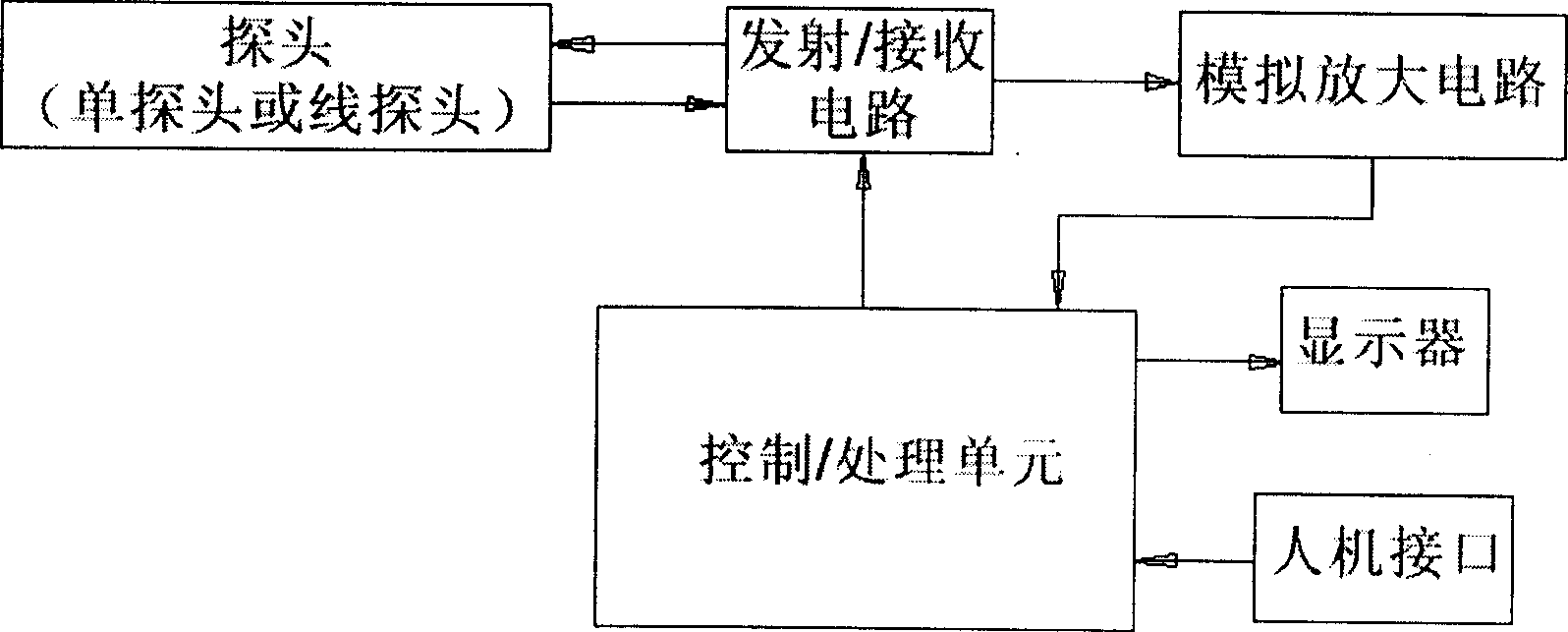
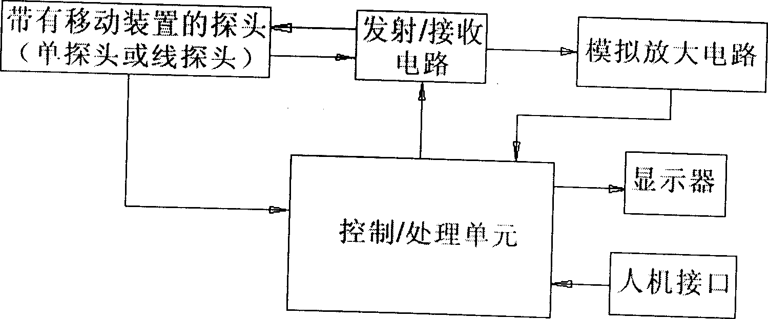
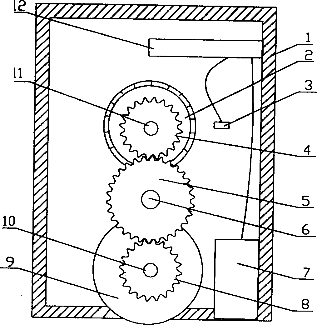
[0027] Circuit composition of the present invention sees figure 1 , its working principle is that the excitation pulse in this device is not repeatedly transmitted by the device itself at a certain frequency and other time intervals, and then received and processed; but the excitation pulse is produced according to the movement of the probe, and is connected with the probe as the probe moves. The linkage device can provide the physical displacement and provide the equipment with the physical position movement signal of the probe at equal intervals. The equipment generates the excitation pulse according to the movement signal, and then generates the ultrasonic wave, which is coupled to the object to be inspected, and receives the ultrasonic echo signal for processing. Uniformly distributed ultrasonic sound rays are generated in the object to be inspected, thereby realizing undistorted B-scan and C-scan. The physical displacement in the probe provides the equipment with the phy...


PUM


Abstract

This invention discloses a ultrasonic wave detector and detection method thereof, which contains ultrasonic wave probe and linkage device, transmitting/receiving circuit, control/process unit, display device and man-machine conversion interface, wherein the ultrasonic wave probe and linkage device having probe position equal displacement moving signal generator composed of mechanical counter or photoelectric mouse structure synchronous moved with probe, generating pulse displacement mark signal of horizontal scale and/or ordinate scale or grid mark signal, synchronous control transmission circuit generating high voltage excitation pulse to probe which generating ultrasonic wave and transmitting to tested object by coupling. Said invention overcomes the image distortion due to non uniform speed movement.

Description

technical field [0001] The present invention relates to an ultrasonic testing device and a testing method, and more specifically relates to an ultrasonic testing device and a testing method applicable to various occasions. Background technique [0002] To achieve B-scanning in ultrasonic testing, wire probes must be used. To achieve C-scan, it is necessary to use the probe array. The so-called line probe is a probe array composed of a single probe on a straight line. After the sound wave is emitted, it looks like a cut surface. The echoes at different depths are represented by different colors or grayscales, which is just like in the workpiece or human tissue. has a facet Figure 1 Sample. The probe array is a surface composed of a single probe arrangement, just like combining a certain number of wire probes to form an ultrasonic transmitting surface. After the sound waves are emitted, they are like many cut surfaces, and the recovered ultrasonic signals can form a three-d...

Claims


Application Information

Patent Timeline
Patent Type & Authority Applications(China)
IPC IPC(8): G01S15/89G01N29/04G03B42/06
CPCG01S15/8906G01S15/8934
Inventor 崔志国
Owner 崔志国
Why Eureka
Try Eureka