Colour filter base board, liquid crystal display device using it and its assembling method

A color filter and liquid crystal display technology, applied in static indicators, optics, instruments, etc., can solve problems such as uneven distribution of liquid crystal layers, liquid crystal materials, water ripple display defects, etc.

Inactive Publication Date: 2006-03-08
AU OPTRONICS CORP
View PDF0 Cites 0 Cited by
  • Summary
  • Abstract
  • Description
  • Claims
  • Application Information

AI Technical Summary

Problems solved by technology

[0004] However, when a large-size TFT-LCD panel is placed upright, due to the pull-down effect of gravity, it is easy to cause uneven distribution of the liquid crystal layer and flow of liquid crystal material, thus forming water ripples on the panel, especially near the bottom of the panel ( mura) and other display defects

Method used


Image

  • Colour filter base board, liquid crystal display device using it and its assembling method
  • Colour filter base board, liquid crystal display device using it and its assembling method
  • Colour filter base board, liquid crystal display device using it and its assembling method

Examples


Embodiment Construction

[0030] Embodiments of the invention will cooperate with Figure 1 to Figure 5 Make a detailed description as follows.

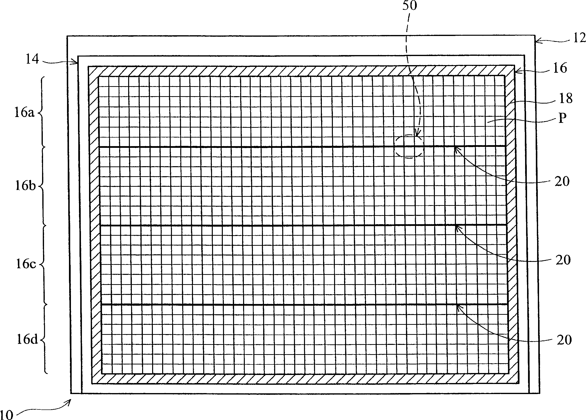
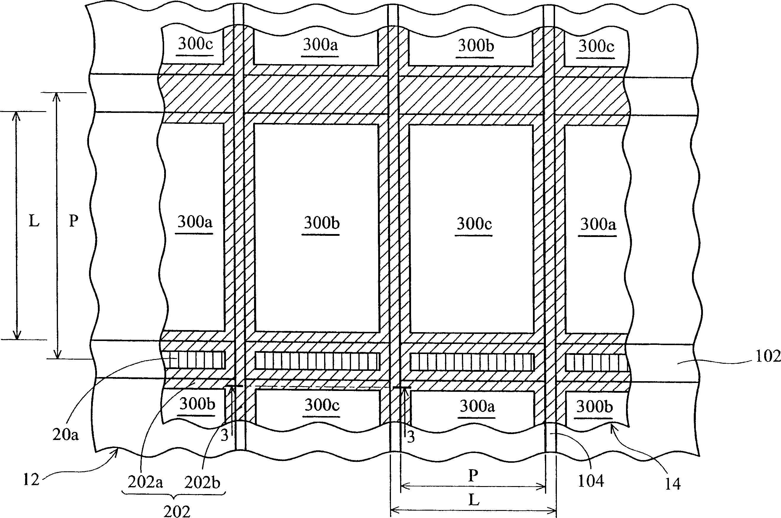
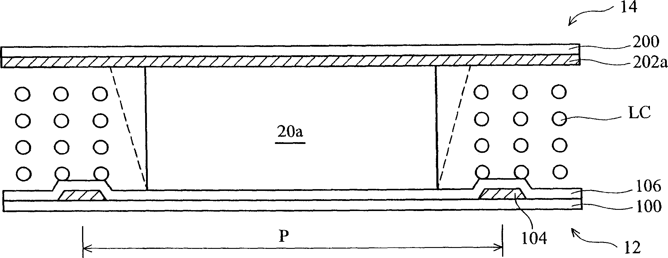
[0031] First please refer to figure 1 is a schematic diagram showing a top view of a liquid crystal display 10 of the present invention. The liquid crystal display 10 includes an array substrate 12 located below and a color filter substrate 14 located above. A display area 16 is disposed between the array substrate 12 and the color filter substrate 14 with a liquid crystal material (not shown) interposed therebetween. The display area 16 is bounded by a sealing layer 18 surrounding the color filter substrate 14. A plurality of display pixels P are formed therein. A plurality of spacer structures 20 are formed in the display area 16 , which are generally arranged laterally, thereby further defining the display area 16 into several sub-display areas 16a, 16b, 16c, 16d. Here, each spacer structure 20 is composed of a plurality of discontinuously formed space...


PUM


Abstract

This invention refers to a color filtering piece substrate, which contains a transparent substrate, light shading layer on said substrate for defining plurality of light penetration area, said light shading layer having plurality of first light shading sections and second light shading sections which are intercrossed, a interval object structure containing plurality of discontinuously set interval object section. Said invention also refers LCD and assembling method using said invention.

Description

technical field [0001] The invention relates to a liquid crystal display (liquid crystal display, LCD), in particular to a color filter substrate for a liquid crystal display. Background technique [0002] Liquid crystal displays (LCDs) have many advantages, such as small size, light weight, and low power consumption. Therefore, LCDs have been widely used in portable computers, mobile phones and other electronic products. A liquid crystal display usually includes two upper and lower substrates with electrodes. In order to maintain a fixed distance between the two substrates, particles with a certain particle size are scattered between the two substrates. These particles are commonly known as spacers. Usually, a thin film transistor used as a switching element is formed on the surface of the lower substrate. The thin film transistor has a gate electrode connected to the scan line, a drain electrode connected to the signal line, and a source electrode connected to the pixel e...

Claims


Application Information

Patent Timeline
Patent Type & Authority Applications(China)
IPC IPC(8): G02F1/133G02F1/1339
Inventor 郑江崇仁陈世烽刘竹育
Owner AU OPTRONICS CORP
Why Eureka
Try Eureka