Layer-stranded optical fiber ribbon cable and production process

A technology of optical fiber ribbon and layer stranding, which is applied in the field of layer stranding optical fiber ribbon cable and production technology, and can solve the problems of restricting the mobility of the optical fiber bundle in the optical fiber ribbon, low installation efficiency, and the inability of effective bending and curling of the optical fiber bundle and other issues to achieve the effect of improving physical properties or temperature performance, avoiding damage or destruction, and ensuring peelable characteristics

Active Publication Date: 2022-03-01
SHANTOU HIGH TECH ZONE AOXING OPTICAL COMM EQUIP +1
View PDF0 Cites 0 Cited by
  • Summary
  • Abstract
  • Description
  • Claims
  • Application Information

AI Technical Summary

Problems solved by technology

[0003] At present, the optical fiber ribbon in the optical fiber ribbon cable is prepared by coating the ribbon resin in a mold and cured by UV grooves. After the photocuring, the molecular chains in the ribbon resin are in a "cross-linked and cured" state, and the resin's The UV curing degree is high, which limits the mobility of the fiber bundle in the fiber ribbon; at the same time, the cured resin coating has a high modulus and poor flexibility, and the fiber bundle cannot be effectively bent and crimped in the fiber ribbon; Moreover, the optical fiber ribbons in the loose tube are placed in a "flat-stacked" manner, that is, another layer of optical fiber ribbons is stacked on top of one layer of optical fiber ribbons, which leads to a small duty ratio of the optical fiber in the loose tube, which cannot Effectively reduce the outer diameter of the loose tube and the weight of the cable itself, causing problems such as higher cost of optical fiber ribbon cable, lower installation efficiency, and higher laying costs

Method used


Image

  • Layer-stranded optical fiber ribbon cable and production process
  • Layer-stranded optical fiber ribbon cable and production process
  • Layer-stranded optical fiber ribbon cable and production process

Examples


Embodiment 1

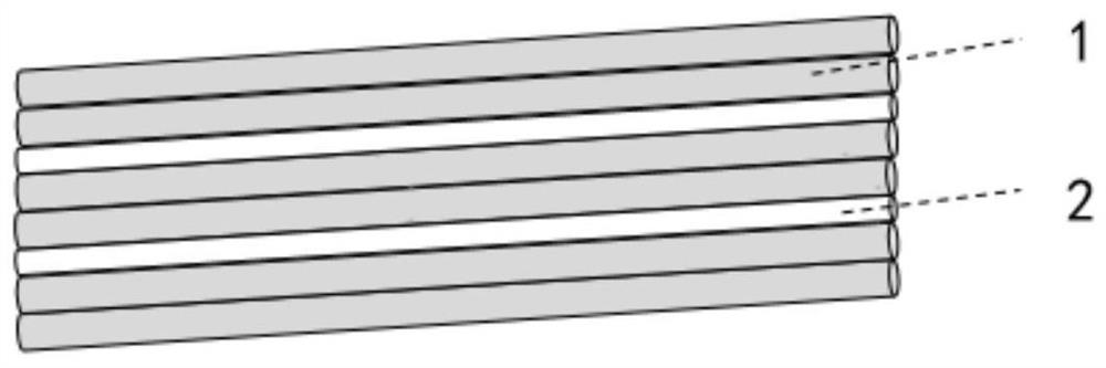
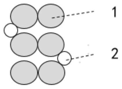
[0033] Such as Image 6 As shown, Embodiment 1 provides a layer-stranded optical fiber ribbon cable, including a plurality of loose tubes 3 in a twisted state and an optical fiber unit installed in the loose tube 3, and the fiber unit and the loose tube A water-blocking filler 4 is filled between them, a central strength member 8 is placed inside a plurality of stranded loose tubes, and a water-blocking tape 7, a metal tape 9 and a sheath layer 6 are placed outside, and the optical fiber unit includes a plurality of bendable The optical fiber ribbon 5, the bendable optical fiber ribbon 5 is a continuous and alternate arrangement of the optical fiber bundle 1 and the bonding layer 2, the optical fiber bundle 1 is formed by combining two optical fibers through UV curing of a photocurable resin, and the bonding layer 2 It is a hot-melt adhesive resin continuously coated between the fiber bundles; the fiber bundle 1 can be bent freely along the axial direction of the adhesive laye...

Embodiment 2

[0052] The structure of embodiment 2 is as Figure 7 As shown, it differs from Embodiment 1 in that: the number of cores of the optical cable is 216 cores, the loose tube 3 is 6 twisted PBT sleeves, and the water blocking filler 4 is Water-blocking powder, the outer diameter of the bonding layer 2 is 120% of the diameter of the optical fiber, the photocurable resin is epoxy resin, the viscosity is 15000cps, the UV curing degree is 70%, and the test condition of MFI (melt index) is: 230 ℃, 2.16kg. The formula used for the bonding layer resin is as follows: 92% polyacrylate, 4% aminosilane, 4% dialkyl peroxide, wherein the melt index of polyacrylate is 40g / 10min, The flexural modulus is 400Mpa; the number of functional groups in the molecular structure of aminosilane is 3. Among them, the peeling force of the bonding layer and the optical fiber bundle is tested on a tensile testing device using a 180° clamp, the tensile rate is 25mm / min, and the peeling force is 1.3N.

Embodiment 3

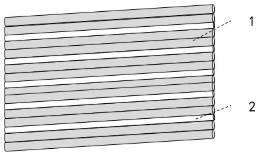
[0054] The structure of embodiment 3 is as Image 6 As shown, it is different from Embodiment 1 in that: the number of cores of the optical cable is 300 cores, the water blocking filler 4 is water blocking powder, and the central strengthening member 8 is GRP. fiber optic ribbon image 3 , 4 As shown, the optical fiber ribbon in a loose tube has 5 layers, and the optical fiber in the optical fiber ribbon has 12 cores. The outer diameter of the bonding layer 2 is 80% of the diameter of the optical fiber. The optical fiber bundle includes two colored optical fibers and a photocurable resin. The photocurable resin is epoxy resin with a viscosity of 13000cps and a UV curing degree of 63%. The test condition of MFI (melt index) is: 230°C , 2.16kg. The formula used for the bonding layer resin is as follows by weight: 90% polyurethane, 4% aminosilane, 6% peroxycarbonate, the melt index of the polyurethane is 60g / 10min, and the flexural modulus is 400Mpa , In the molecular struct...


PUM

PropertyMeasurementUnit
melt flow indexaaaaaaaaaa
flexural modulusaaaaaaaaaa
melt flow indexaaaaaaaaaa

Abstract

The invention discloses a layer-stranded optical fiber ribbon cable and its production process, which includes a loose tube and an optical fiber unit installed in the loose tube, a central strengthening member is placed inside the stranded loose tubes, and a water blocking belt is placed outside , a metal ribbon and a sheath layer, the optical fiber unit includes a multi-layer bendable optical fiber ribbon, the bendable optical fiber ribbon is a continuous and alternate arrangement of optical fiber bundles and adhesive layers, and the optical fiber bundle is at least two optical fibers passing through The photocurable resin is UV-cured and formed together, and the adhesive layer is a hot-melt adhesive resin layer continuously coated between the optical fiber bundles, so that the optical fiber bundles can be bent along the axial direction of the adhesive layer. The layer-stranded optical fiber ribbon cable prepared by the present invention, because the optical fiber bundle has bendability and mobility in the optical fiber ribbon, thereby improving the duty cycle of the optical fiber in the loose tube and the fiber packing density of the optical fiber in the optical cable, and can reduce the fiber density at the same time. The outer diameter of the optical cable is small, reducing the weight of the optical cable itself, which is beneficial to saving the installation and welding time of the optical fiber ribbon optical cable, and improving the installation and laying efficiency of the optical cable.

Description

technical field [0001] The invention relates to the technical field of communication optical fiber cables, in particular to a layer-stranded optical fiber ribbon cable and a production process. Background technique [0002] Due to the high integration of optical fibers, the compact structure of the optical fiber cable, and less routing resources, it can effectively reduce the cost of optical cable fusion and improve the efficiency of installation and laying. Thanks to these advantages, the optical fiber ribbon cable is used in the metropolitan area network and access network. has been widely used. Stranded optical fiber ribbon cables are generally formed by twisting loose tubes on tensile elements. Each loose tube uses 6-core or 12-core optical fiber ribbons, which are stacked with different numbers of optical fiber ribbons. Due to the layer-stranded The structure is multi-tube twisted, and the number of fiber cores of the optical fiber ribbon cable is large, which can meet...

Claims


Application Information

Patent Timeline
Patent Type & Authority Patents(China)
IPC IPC(8): G02B6/44
CPCG02B6/4403G02B6/441G02B6/443G02B6/4434G02B6/4432G02B6/4479G02B6/4486
Inventor 杨向荣罗俊超祁林刘宏超黄杰
Owner SHANTOU HIGH TECH ZONE AOXING OPTICAL COMM EQUIP
Why Eureka
Try Eureka