Display panel driving circuit

A technology of display panels and driving circuits, applied in static indicators, instruments, etc., can solve problems such as uneven brightness, and achieve the effect of reducing uneven brightness

Inactive Publication Date: 2006-03-08
SEIKO EPSON CORP
View PDF1 Cites 2 Cited by
  • Summary
  • Abstract
  • Description
  • Claims
  • Application Information

AI Technical Summary

Problems solved by technology

On the other hand, in the frame inversion method of the LCD panel described above, the problem is not the flicker but the unevenness of brightness within one frame.

Method used


Image

  • Display panel driving circuit
  • Display panel driving circuit
  • Display panel driving circuit

Examples


Embodiment Construction

[0031] Hereinafter, preferred embodiments for carrying out the present invention will be described in detail with reference to the accompanying drawings. In the following embodiments, an LCD panel is used as a display panel.

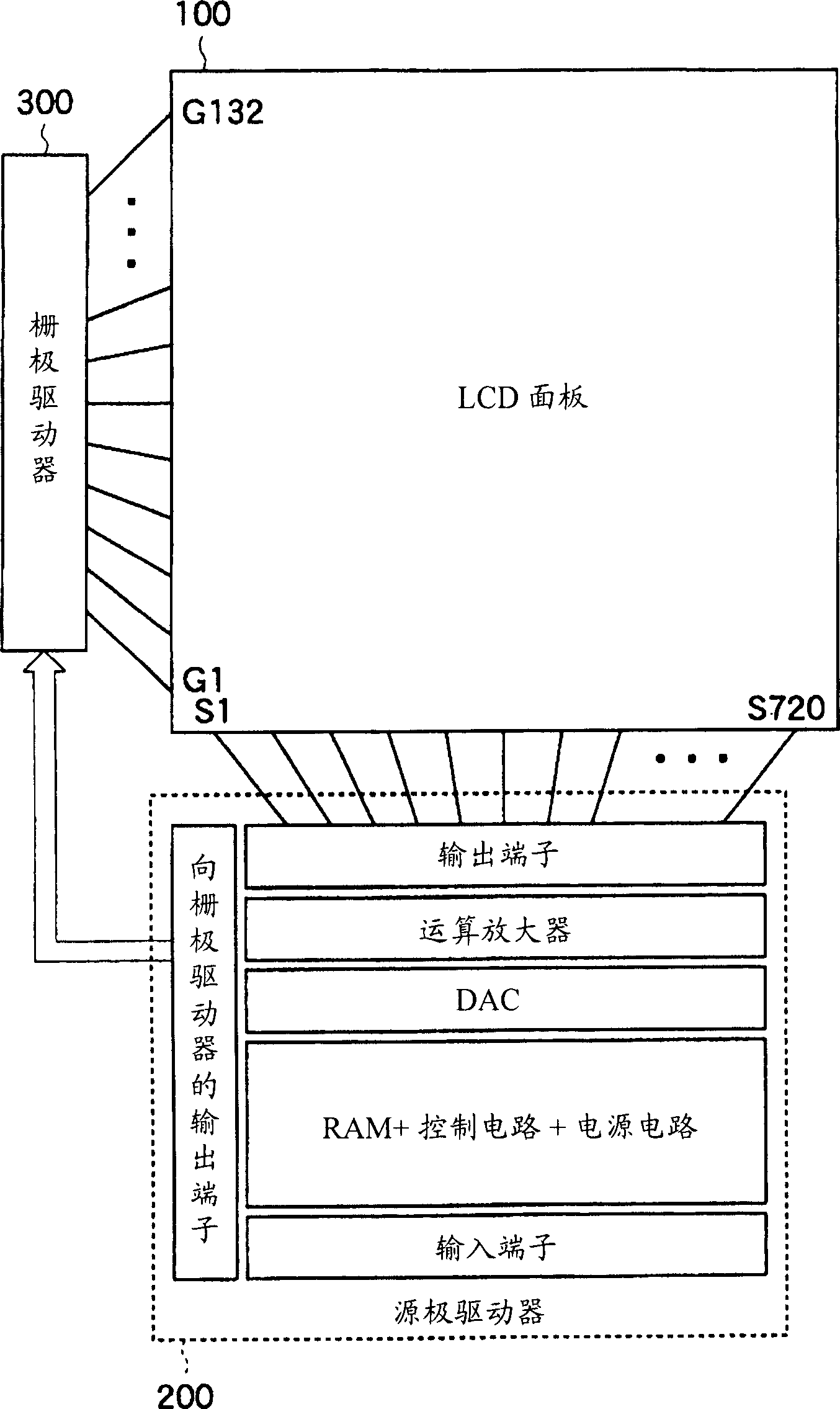
[0032] figure 1 The connection relationship between the display panel driving circuit and the LCD panel according to one embodiment of the present invention is shown. In the LCD panel 100 , for example, corresponding to 720×132 dots, the same number of TFTs are arranged in a two-dimensional matrix. To drive the LCD panel 100, a display panel driving circuit (source driver) 200 that drives the sources of these TFTs is connected to the source lines S1 to S720, and a display panel driving circuit (gate driver) 300 that drives the gates of these TFTs is connected to to the gate lines G1-G132.

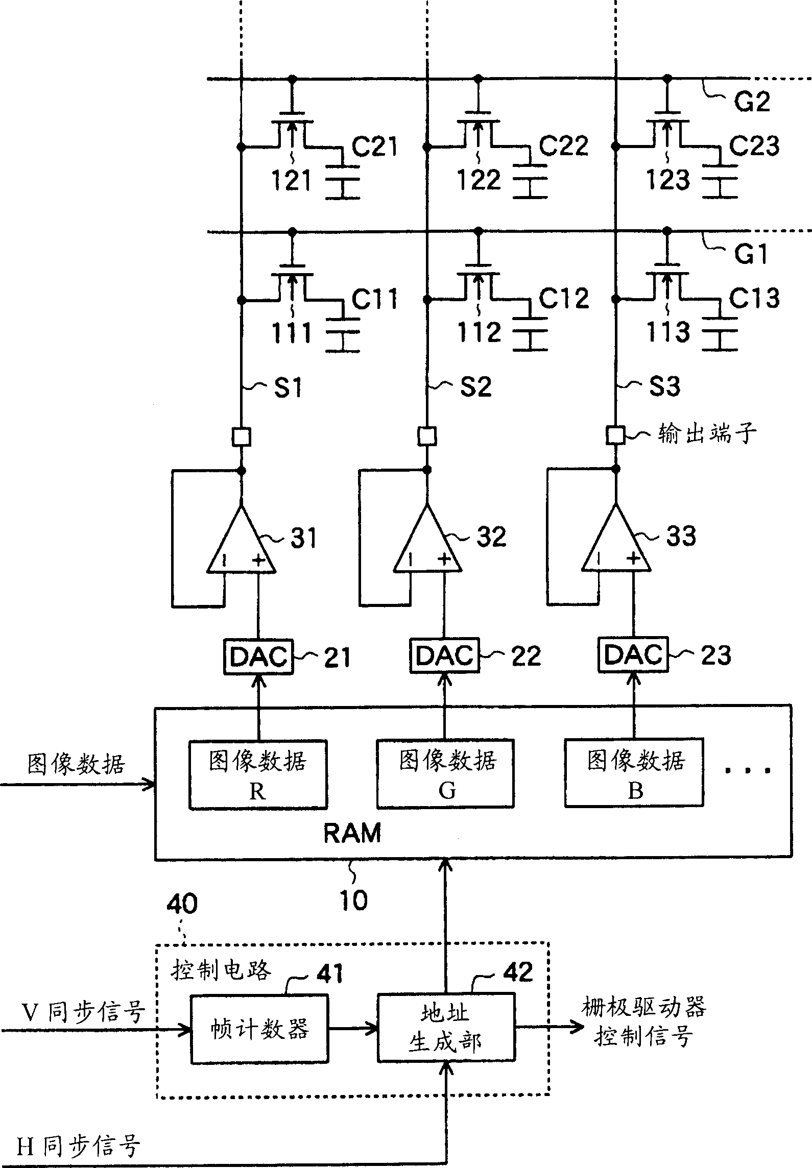
[0033] In the source driver 200, in addition to a RAM, a control circuit, a power supply circuit, a DAC (Digital to Analog Converter: Digital / Analog Converter), a...


PUM


Abstract

To provide a display panel driving circuit which employs a frame inversion system with low power consumption to drive a display panel and which decreases irregular luminance in one frame. The display panel driving circuit is equipped with: a memory means 10 to temporarily memorize input image data; a controlling means 40 to control the read-out operation of image data in one line from the memory means in such a manner that the display start lines in the display panel differ in every predetermined number of frame periods; and image signal supply means 21 to 33 to convert the image data of each line successively read out from the memory means into a plurality of analog image signals and to supply the image signals to the display panel.

Description

technical field [0001] The present invention relates to a display panel driving circuit for driving a display panel, especially a display panel driving circuit for driving an LCD (Liquid Crystal Display: liquid crystal display) panel with a plurality of TFTs (Thin Film Transistor: Thin Film Transistor) built in. Background technique [0002] A display panel drive circuit (source driver) that drives the source of the TFTs and a display panel drive circuit (gate driver) that drives the gates of the TFTs are connected to an LCD panel that incorporates multiple TFTs. In the source driver, the image data of each row sequentially read from RAM (Random Access Memory: Random Access Memory) is converted into analog image signals, and these image signals are supplied to the sources of the TFTs. [0003] On the other hand, the gate driver generates a gate potential for turning on the TFTs in sequentially selected rows and supplies it to the gate of the TFT, and generates a voltage appl...

Claims


Application Information

Patent Timeline
Patent Type & Authority Applications(China)
IPC IPC(8): G09G3/36G02F1/133
CPCG09G3/3688G09G2310/027G09G2320/0233G09G3/3696G09G3/3655G09G3/3614G09G2310/02
Inventor 牧克彦
Owner SEIKO EPSON CORP
Why Eureka
Try Eureka