High-frequency apparatus

A high-frequency equipment and frame technology, which is applied to the structural parts of electrical equipment, electrical components, magnetic field/electric field shielding, etc., can solve the problems of poor inspection performance, enlarged strip substrate, deviation of machining accuracy and assembly state, etc. Achieve the effect of correct position, easy unloading and reduction of overhang

Inactive Publication Date: 2006-03-15
ALPS ALPINE CO LTD
View PDF1 Cites 0 Cited by
  • Summary
  • Abstract
  • Description
  • Claims
  • Application Information

AI Technical Summary

Problems solved by technology

[0012] In conventional high-frequency equipment, the shield box 51 is held by a jig and inspected in a positioned state during the electrical inspection after assembly. Due to deviations in the assembly state, etc., the probe installed on the inspection device cannot be correctly contacted with the prescribed wiring pattern 53, and the inspection performance is deteriorated.
[0013] In addition, since the circuit substrate of conventional high-frequency equipment forms the delivery hole 56 on the ear portion 57, it is necessary to enlarge the ear portion 57 and enlarge the strip-shaped substrate 55. As a result, the yield decreases and the cost of the circuit substrate 52 is high. question

Method used


Image

  • High-frequency apparatus
  • High-frequency apparatus
  • High-frequency apparatus

Examples


Embodiment Construction

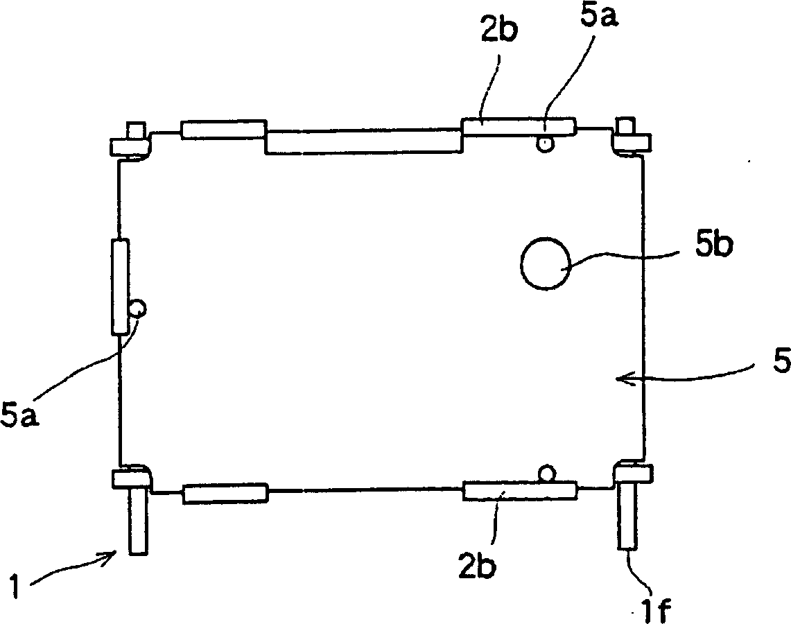
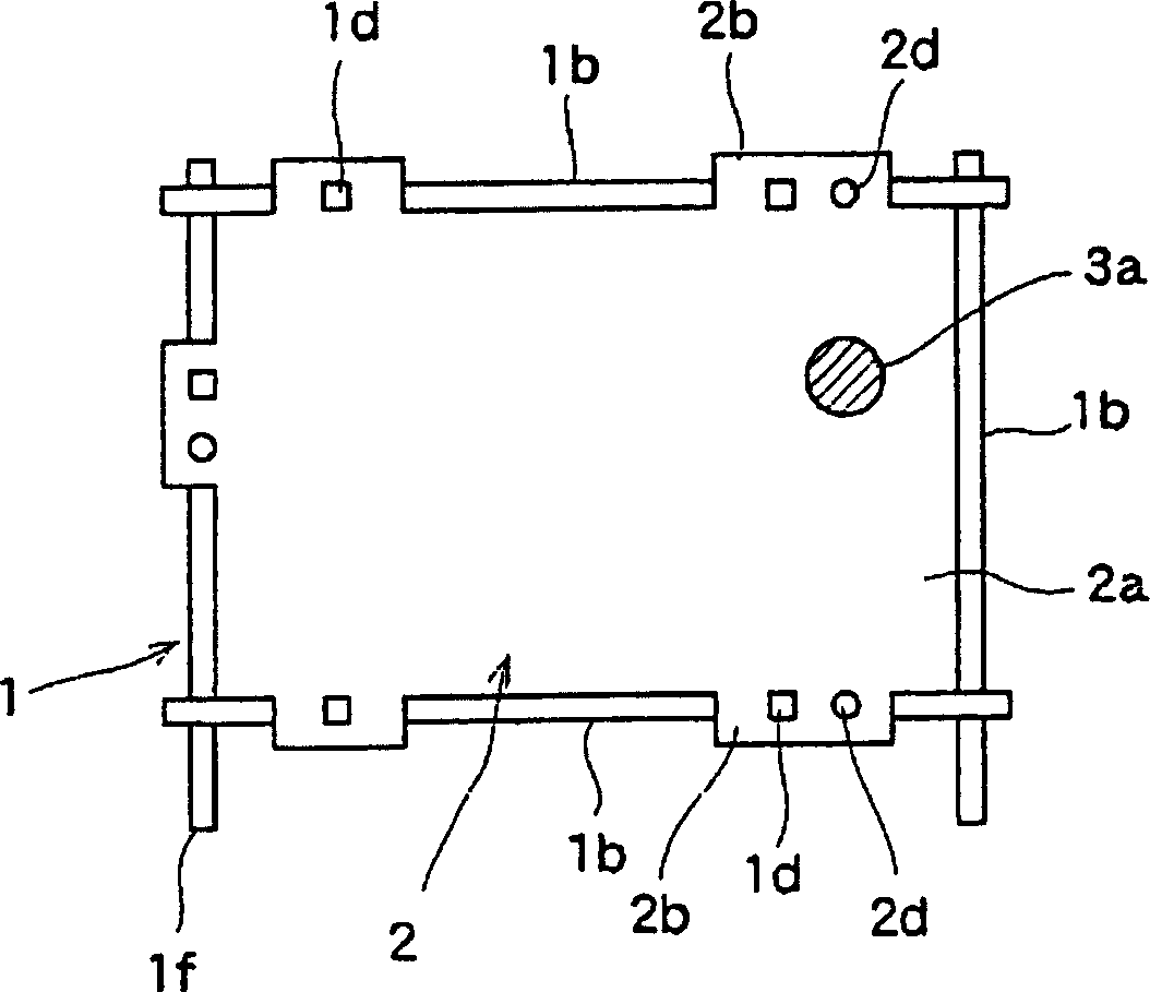
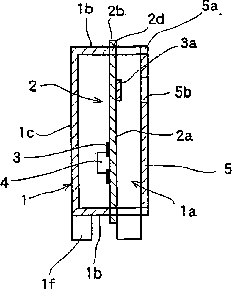
[0038] Next, a schematic diagram of the high-frequency device of the present invention will be described. figure 1 is a front view of the high-frequency device of the present invention, figure 2 It is the front view of the state which removed the cover body of the high frequency equipment of this invention, image 3 It is a sectional view of main parts of the high-frequency equipment of the present invention, Figure 4 It is an exploded perspective view of a frame body and a circuit board of a high-frequency device of the present invention, Figure 5 It is an explanatory drawing showing the inspection method of the high-frequency equipment of the present invention, Figure 6 It is an explanatory drawing showing the manufacturing method of the circuit board of the high-frequency device of this invention.

[0039] Below, based on Figure 1 ~ Figure 4The configuration of the high-frequency device of the present invention will be described. A box-shaped frame body 1 formed ...


PUM


Abstract

The invention provides a high frequency equipment which has an inexpensive circuit board and can be reliably inspected. In the high frequency equipment, the extension 2b of a circuit board 2 is provided with a mount hole 2c for receiving the projection 1d of a frame 1 thereinto and mounting the circuit board 2 thereto, and with a positioning hole 2d capable of receiving a guide rod 8 therein. Thus, when the device after being assembled is inspected, a probe 9 can be positioned with use of the positioning hole 2d having a wiring pattern 3 provided thereto as a reference, the position of the probe 9 relative to the wiring pattern 3 can be made accurate, and the device can be reliably inspected. Further, upon manufacturing the circuit board, the positioning hole 2d provided in the extension 2b of the circuit board 2 can be used also as a feed hole, a strip-shaped substrate 10 for use in manufacture of the circuit board 2 can be made small, and therefore an expensive circuit board can be obtained.

Description

technical field [0001] The present invention relates to a high-frequency device suitable for use in a television tuner. Background technique [0002] When explaining the illustrations of conventional high-frequency equipment, Figure 7 It is a perspective view of conventional high-frequency equipment, Figure 8 It is an explanatory diagram showing a conventional method of manufacturing a circuit board of a high-frequency device. Below, if referring to Figure 7 , Figure 8 The structure of the conventional high-frequency equipment will be described. The shield box 51, which is a box-shaped frame made of metal, has a plurality of wall portions 51b surrounding the periphery in a state where the opening portion 51a is provided, and a wall from the side of the opening portion 51a. A plurality of projections 51c protruding from the end surface of the portion 51b, and a notch 51d provided in the wall portion 51b at the base of the projections 51c. [0003] The circuit board 52 ...

Claims


Application Information

Patent Timeline
Patent Type & Authority Applications(China)
IPC IPC(8): H05K9/00H05K7/00
Inventor 杉森善雄
Owner ALPS ALPINE CO LTD
Why Eureka
Try Eureka