

Coating device and method
A coating device and coating head technology, which is applied to the surface coating liquid device, spray device, coating, etc., can solve the problem of difficulty in drawing the paste pattern into the desired shape and position
- Summary
- Abstract
- Description
- Claims
- Application Information
AI Technical Summary
Problems solved by technology
Method used
Image

Examples
Embodiment 1
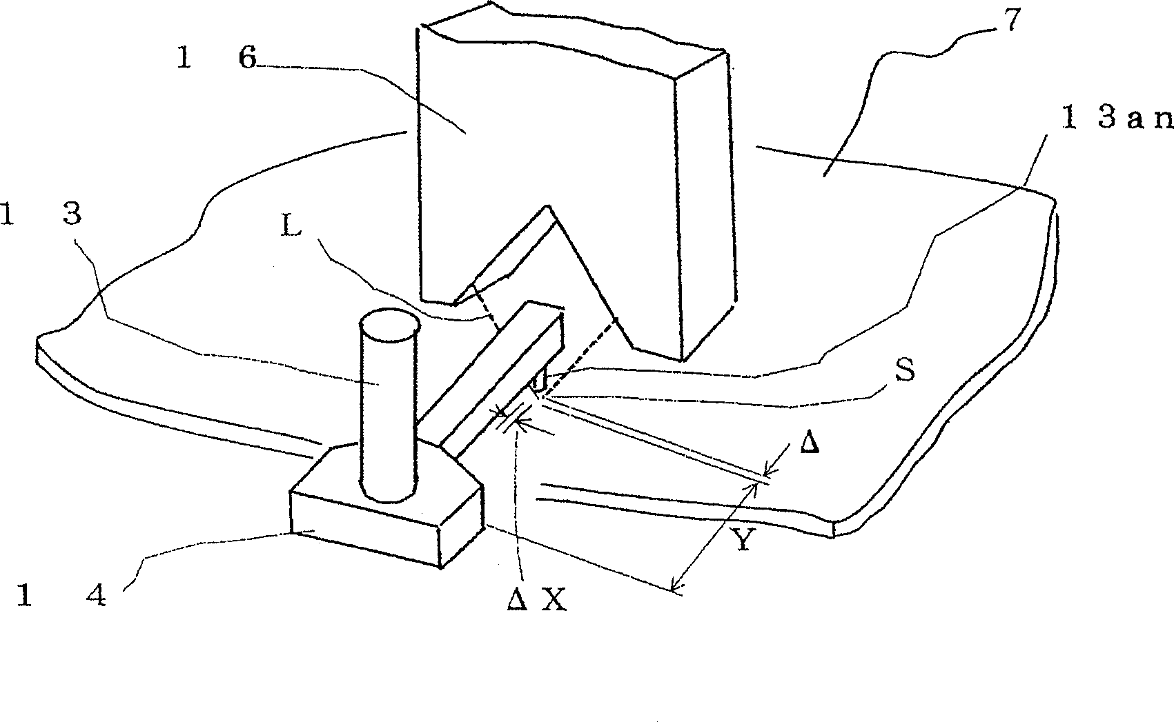
[0015] One embodiment of the present invention will be described below with reference to the drawings. In this embodiment, an apparatus for drawing a paste pattern (sealing material pattern) on a substrate surface is exemplified, but similarly, it can also be applied to a dropping apparatus for dropping liquid crystal on a substrate using a gate-shaped frame structure.
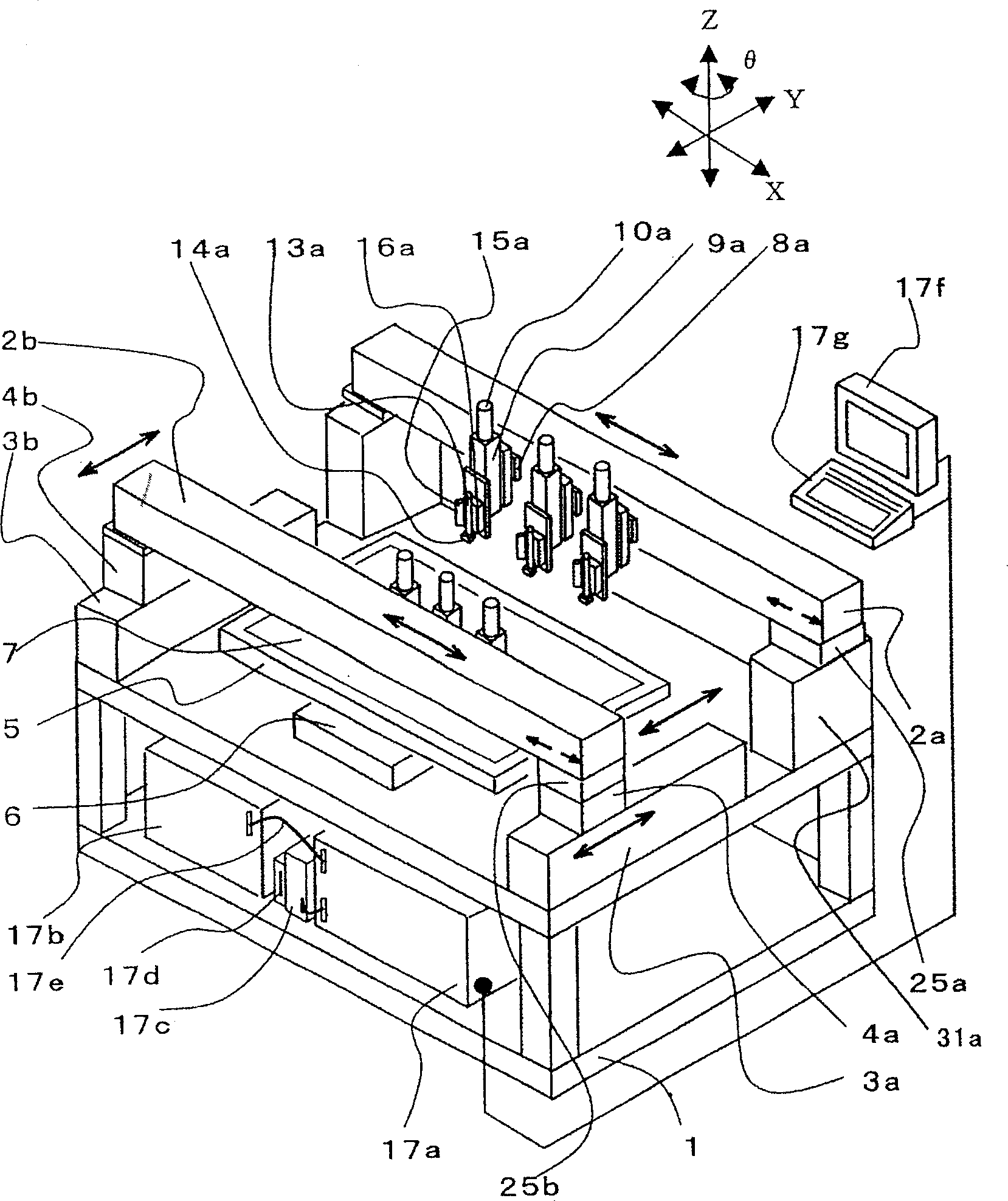
[0016] figure 1 It is a perspective view showing one embodiment of the paste applicator of the present invention. In addition, in order to avoid trouble, a to f are added to the number of each part in the following description for the number of each part of the several applicator head installed relatively.
[0017] One end of each frame (beam) 2a, 2b is fixed to the support leg 31a or the linear motor 4b so as not to move in the X-axis direction. Moreover, the other end side of each beam 2a, 2b is supported by the thermal expansion guide rail 25a, 25b which can move in the X-axis direction. The structure of...
PUM
 Abstract
Description
Claims
Application Information