Differential thrust balance device for rotary fluid machinery

A technology of thrust balance and fluid machinery, applied in the direction of mechanical equipment, non-variable pumps, machines/engines, etc., can solve the fluid leakage and throttle gap pressure difference changes, affect the size of the axial balance force, axial balance Force error and other problems, to achieve the effect of reducing alarms and chain shutdowns, preventing damage to thrust bearings, and preventing alarm chain shutdowns

Inactive Publication Date: 2006-03-22
BEIJING UNIV OF CHEM TECH
View PDF1 Cites 26 Cited by
  • Summary
  • Abstract
  • Description
  • Claims
  • Application Information

AI Technical Summary

Problems solved by technology

[0015] (1) Even a pressure differential thrust balance device with a certain strain capacity has limited and inaccurate adaptability to axial force changes caused by changes in working load and fluid properties
[0016] (2) It is impossible to overcome the influence of design and manufacturing errors, resulting in permanent axial balance force errors
[0017] (3) Unable to respond to changes in one's own condition
For example, the fluid throttling gap becomes larger due to wear, or factors such as scaling, blockage, or rust become s

Method used


Image

  • Differential thrust balance device for rotary fluid machinery
  • Differential thrust balance device for rotary fluid machinery
  • Differential thrust balance device for rotary fluid machinery

Examples


Embodiment 1

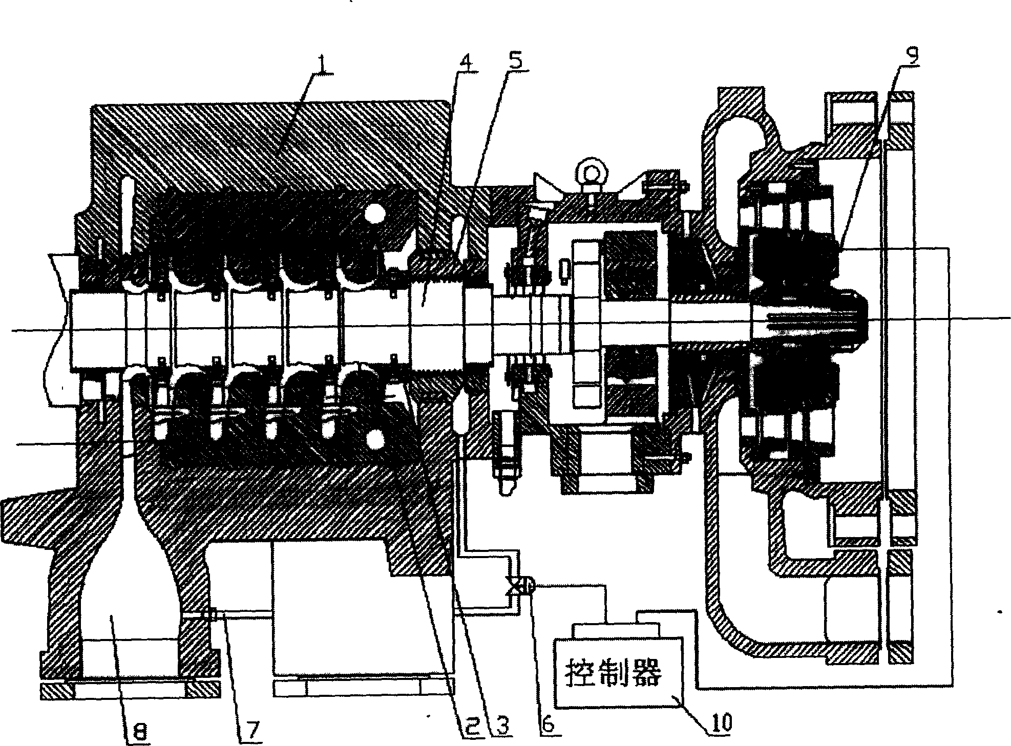
[0054] see figure 1 . The fluid flows from the high-pressure zone 2 of a compressor 1 exit through a high-pressure fluid channel 3 to the thrust balance disc 4 coaxial with the rotor, leaks through the annular leakage gap 5 to the thrust balance disc, and then passes through a fluid flow regulating device 6 The pressure relief pipeline (ie, the low-pressure fluid channel 7) flows to the low-pressure zone 8 at the inlet of the compressor.

[0055] The signal measured by the thrust detection device 9 installed at the shaft end is sent to the controller 10. The controller 10 controls the fluid flow adjustment device 6 according to the signal measured by the thrust detection device 9, which changes the compressor balance plate 4 The flow to the low pressure zone 8 at the compressor inlet.

[0056] The action process of the present invention is as follows: when the residual axial force becomes larger, the signal measured by the thrust detection device 9 changes, and this signal is sen...

Embodiment 2

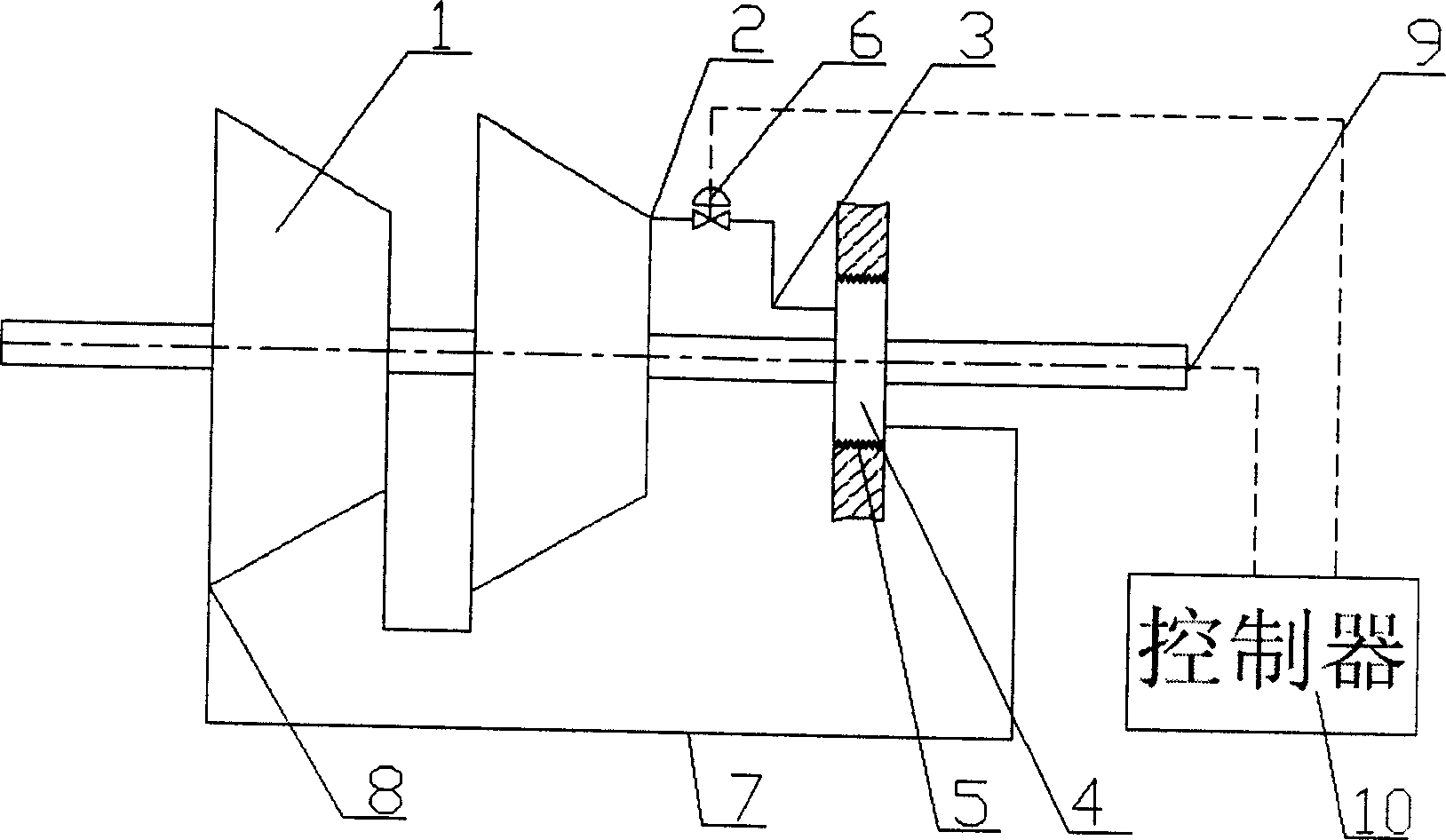
[0064] see figure 2 Similar to Example 1, the difference is that the front of the thrust balance disk 4 is connected to the high pressure zone 2 through a tubular fluid channel 3, and the fluid flow regulating device 6 is located in the tubular fluid from the high pressure zone 2 to the thrust balance disk 4 On channel 3. The thrust balance plate 4 is connected with the low pressure zone 8 through the pressure relief pipeline 7. The fluid flow adjustment device 6 is used to control the fluid flow from the high pressure zone 2 to the thrust balance disc 4 to change the pressure difference before and after the thrust balance disc, thereby changing the magnitude of the axial balance force.

Embodiment 3

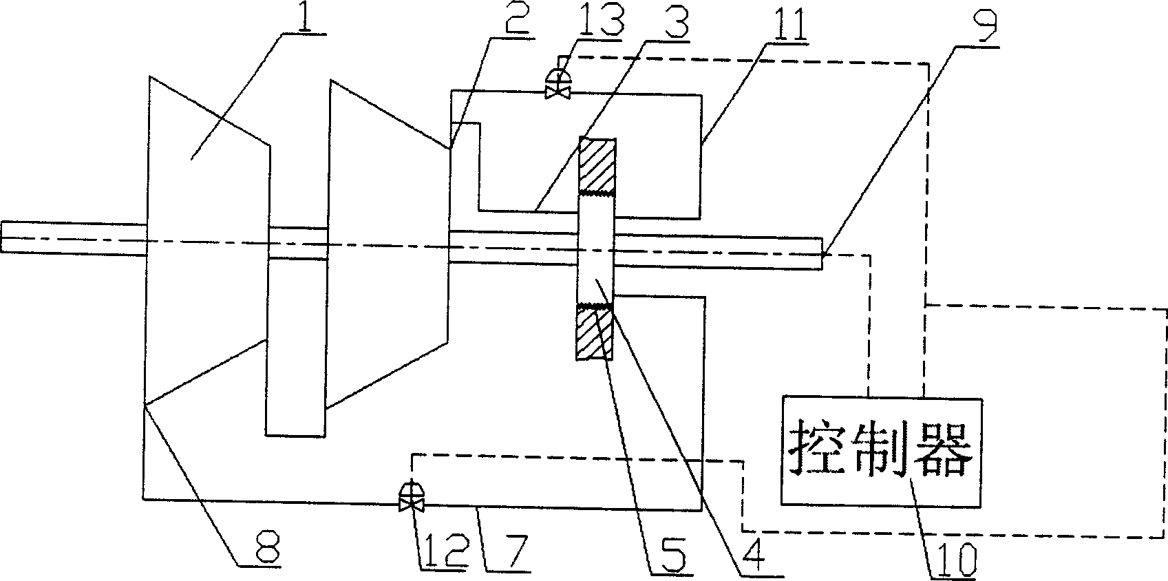
[0066] see image 3 . Similar to Example 1, the difference is that after the thrust balance disk 4, in addition to communicating with the low pressure zone 8 through a pressure relief pipe 7, it also communicates with the high pressure zone 2 through a pipe (the second high pressure fluid passage 11). Correspondingly, the flow regulating device is composed of a low-pressure flow regulating valve 12 located on the low-pressure fluid pipeline 7 and a high-pressure flow regulating valve 13 located on the second high-pressure fluid passage 11. The thrust balance plate 4 is communicated with the high pressure zone 2 through a high pressure fluid channel 3 in front.

[0067] Here, the function of the second high-pressure fluid pipe 11 and the high-pressure flow regulating valve 13 is: when the pressure difference of the balance disc needs to be reduced, the balance disc 4 can be filled with pressure to improve the response speed of the adjustment process.

[0068] Here, the controller 9...


PUM


Abstract

The present invention relates to differential thrust balance device, and is one kind of differential thrust balance device for rotary fluid machinery. The present invention includes thrust balance device connected to the rotating shaft of rotary fluid machinery, leakage interval for fluid medium to flow from the high pressure area to the low pressure area, thrust detecting unit, controller and flow regulator. The shaft displacement sensor, the oil film thickness sensor and the thrust detecting sensor are installed on the rotary fluid machinery. The flow regulator receives the control signal from the controller to regulate the flow rate through the fluid passage so as to regulate the pressure difference across the balance disc and thus the balance thrust. The present invention is used in the axial force balance of rotary fluid machinery to avoid the damage of the apparatus caused by axial thrust change.

Description

Technical field: [0001] The invention relates to a thrust balance device in a rotating fluid machine, in particular to a differential pressure type thrust balance device on a rotating shaft. Background technique: [0002] In the operation of rotating fluid machinery (including pumps, fans, compressors, expanders, turbines, water turbines, propellers, turbine engines, etc.), due to the interaction between the rotor and the fluid, an axial force will be generated. The differential pressure type thrust balance device offsets most of the thrust and maintains a certain amount of residual axial force, thereby greatly reducing the load of the thrust bearing. The most commonly used balancing device is to introduce high-pressure fluid from the high-pressure end of the equipment, and then the fluid leaks to the low-pressure end of the equipment through a throttling channel. The pressure difference between the high-pressure end and the low-pressure end acts on a certain part of the rotor (u...

Claims


Application Information

Patent Timeline
IPC IPC(8): F04D15/00F04D27/02
Inventor 高金吉江志农张鹏张雪
Owner BEIJING UNIV OF CHEM TECH
Why Eureka
Try Eureka