Power push button device

A button and power supply technology, applied in circuits, electrical switches, electrical components, etc., can solve the problems of friction of the hook portion 22, increase costs, etc., and achieve the effects of reducing material costs, reducing friction, and simplifying the production process

Inactive Publication Date: 2006-03-22
LEIJIN ELECTRONIC SHENYANG CO LTD
View PDF0 Cites 2 Cited by
  • Summary
  • Abstract
  • Description
  • Claims
  • Application Information

AI Technical Summary

Problems solved by technology

[0009] But, because as mentioned above, conventional power button device is to make above-mentioned box hook portion 22 the form that protrudes, so when above-mentioned button box 20 is inserted, friction phenomenon occurs in above-mentioned hook portion 22.
[0010] In addition, since the above-mentioned button case 20 is rigidly inserted, there is a problem that a large amount of force is required in the assembly process and repair.
[0011] In addition, since a very long guide strip 21 is made on the outer peripheral surface of the above-mentioned button box 20, unnecessary frictional force is generated during assembly, and the problem of increasing the cost in the manufacturing process is increased simultaneously.

Method used


Image

  • Power push button device
  • Power push button device
  • Power push button device

Examples


Embodiment Construction

[0036] The specific implementation examples of the present invention will be described in detail below in conjunction with the accompanying drawings, however, they are not limited by the examples.

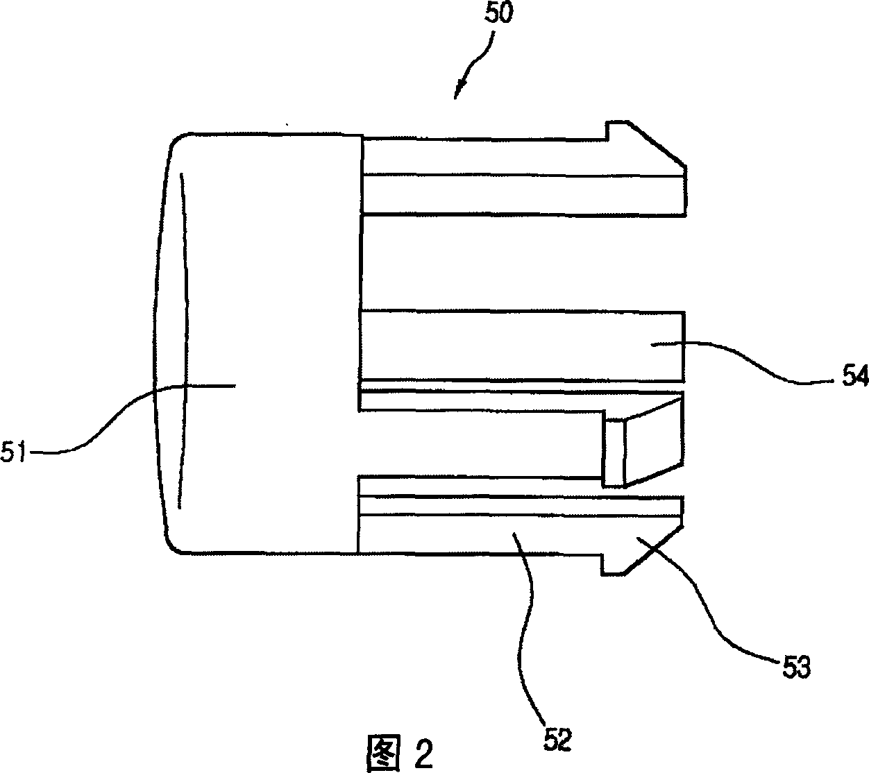
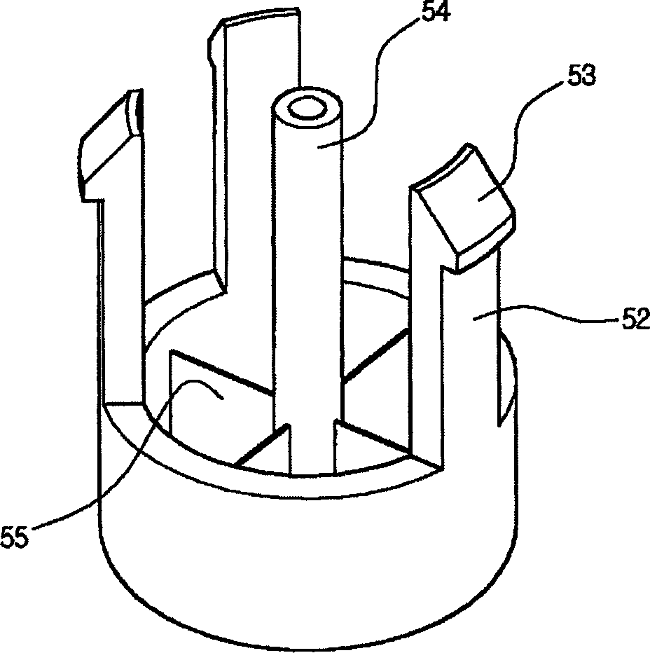
[0037] Fig. 2 is a schematic side view of the power button of the present invention, image 3 It is a schematic bottom view of the power button of the present invention.

[0038] Referring to Figure 2 and image 3 , the power button 50 of the present invention is composed of the following parts: the button top 51 that the user's hand touches; The pressing sleeve 54 of the contact switch on the PCB; the root of the above-mentioned pressing sleeve 54 is made with mutually symmetrical support pressing sleeve supporting legs 55; the bottom surface of the above-mentioned button top 51 is in order to prevent the above-mentioned button top 51 from advancing / Or the offset when retreating has made the guide leg 52; the terminal end of the above-mentioned guide leg 52 is made into a hook ...


PUM


Abstract

This invention relates to a power supply button device including a press button part moving to and fro along with a user, a box hook part capable of closely connecting with the product out of it and a button box at the same gap with the box hook part and presenting flexible buffer hole to said box hook part, which can plug the button box into the front operation disk easily with a small force.

Description

technical field [0001] The invention relates to a power button device of an electronic product, in particular to a power button device for easily inserting the button box into the body of the electronic product. Background technique [0002] Generally speaking, in televisions, audio devices or electronic computers and other electronic products, the pressing action of the power button causes the contact switch mounted on the printed circuit board inside the electronic product to be pressed or released to perform the specified function. function, for which a power button must be inserted and installed on the control panel on the front of the electronics. [0003] figure 1 is a schematic diagram of a conventional power button device. The traditional power button device is composed of a push button part used by the user to turn on or off the TV and other electronic products and a box in which the above button part is installed. [0004] To explain in detail, the above-mention...

Claims


Application Information

Patent Timeline
IPC IPC(8): H01H13/02H01H13/04
Inventor 权硕浩
Owner LEIJIN ELECTRONIC SHENYANG CO LTD
Why Eureka
Try Eureka