Transmission path simulator and radio device evaluation method

A channel emulation, wireless device technology, applied in the direction of instruments, communication between multiple stations, transmission systems, etc., can solve the problem of digital baseband processing unit confirmation detection, inability to perform performance evaluation correctly, inability to perform AGC control and AFC control And other issues

Inactive Publication Date: 2006-03-29
PANASONIC CORP
View PDF1 Cites 3 Cited by
  • Summary
  • Abstract
  • Description
  • Claims
  • Application Information

AI Technical Summary

Problems solved by technology

[0019] However, the existing channel emulator is based on the premise that the analog baseband processing units 42 and 52 and the radio frequency circuits 43 and 53 are all completed to an operable state except for the digital baseband processing units 41 and 51 of the device being developed.
In particular, since the development of the radio frequency circuit 53 in the receiving system 50 has not progressed to a state where the operation is possible, the AGC control and the AFC control cannot be performed, so the performance evaluation cannot be performed correctly
[0020] In this way, the operation of the digital baseband processing units 41 and 51, which is the central part of the process, cannot be checked for confirmation until the radio frequency circuits 43 and 53 (especially the radio frequency circuit 53 of the receiving system) are completed.
This leads to the problem of reduced development efficiency

Method used


Image

  • Transmission path simulator and radio device evaluation method
  • Transmission path simulator and radio device evaluation method
  • Transmission path simulator and radio device evaluation method

Examples


Embodiment approach 1

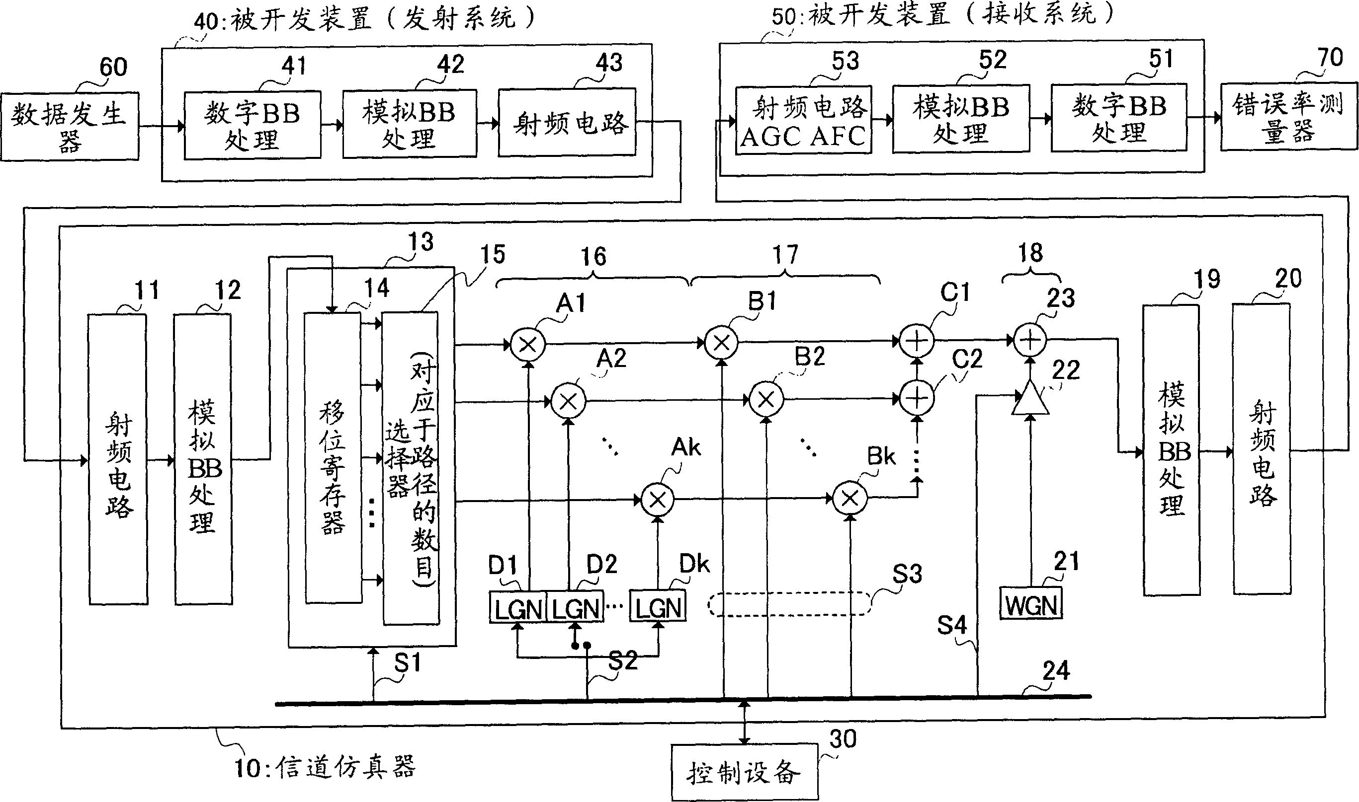
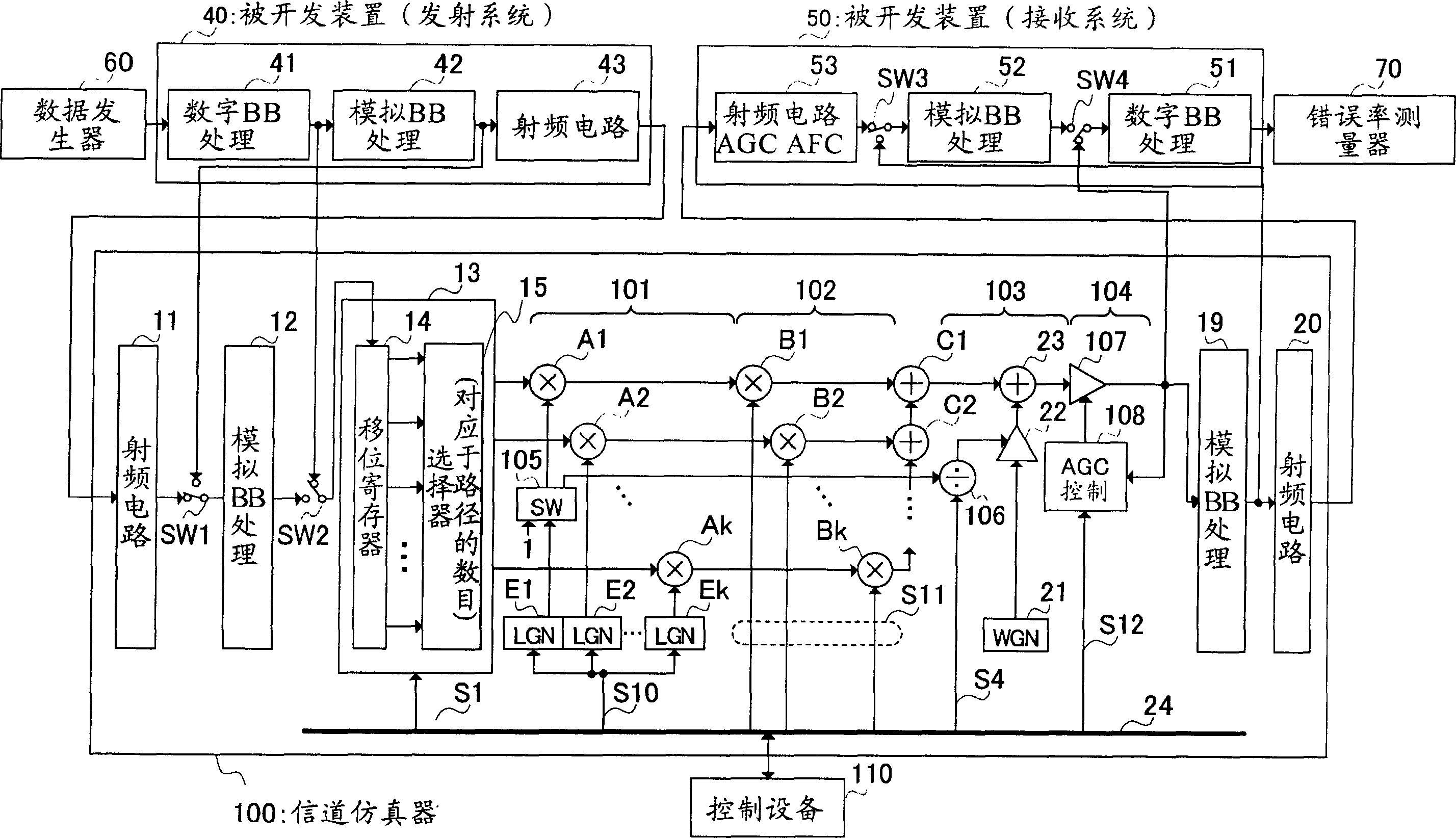
[0040] figure 2 The structure of the channel emulator according to Embodiment 1 of the present invention is shown. Wherein, the same parts as in FIG. 1 use the same reference numerals. In addition, descriptions of the same parts as those in Fig. 1 are omitted. And, same as Fig. 1, every line except the line of the signal of radio frequency circuit 43 and 20 all represent including I channel (in-phase, i.e. the real part of a complex number) and Q channel (90 degree phase shift, i.e. the real part of the complex number) Imaginary part) of the two baseband signal lines.

[0041] In the channel emulator 100 , a switch SW1 is provided between the radio frequency circuit 11 and the analog BB processing unit 12 , and a switch SW2 is provided between the analog BB processing unit 12 and the multipath signal generating unit 13 . In this way, in the channel emulator 100, the output signal from the digital BB processing unit 41 of the transmission system 40 can be directly input thro...

Embodiment approach 2

[0079] Figure 5 The structure of the channel emulator according to Embodiment 2 of the present invention has been explained, wherein with figure 2 The same parts are denoted by the same reference numerals. The channel emulator 200 in this embodiment is the same as the channel emulator 100 in Embodiment 1 except that the transmit analog adjustment unit 201 is arranged before the multipath signal generation unit 13 and the receive analog adjustment unit 202 is arranged after the automatic gain control unit 104 have the same structure.

[0080] Thus, in the channel emulator 200, the output signal of the digital BB processing unit 41 is input through the transmission analog adjustment unit 201, the signal processed by the transmission analog adjustment unit 201 is subjected to the same channel simulation as that in Embodiment 1, and the The same channel analog signal as in Embodiment 1 is output to the digital BB processing unit 51 of the receiving system 50 after being process...


PUM


Abstract

During a one-path transmission path simulation, the entire signal level is maintained constant and a receiver noise imitating an SNR fluctuation caused by fading is added by a receiver noise addition section (103). During a multi-path transmission path simulation, only the amplitude fluctuation caused by fading is given to a signal of each path by an instantaneous fluctuation giving section (101) and a short-long interval fluctuation giving section (102) and the signal level of the paths synthesized by an automatic gain control section (104) is made constant. Thus, it is possible to evaluate the transmission path performance of the digital base band processing section (41) without waiting for development of a radio circuit (53), i.e., without using an AGC circuit or an AFC circuit in the reception system (50).

Description

technical field [0001] The invention relates to a channel emulator for simulating a wireless channel to evaluate a wireless device, and a method for evaluating the wireless device. Background technique [0002] Usually, in the development of mobile phones, base stations of mobile phones, and mobile terminals (MT) and access points (APs) of wireless local area networks (LAN), a device that simulates wireless channels, that is, a channel emulator, is needed as a device to be developed. Environment for device performance evaluation. [0003] By comparing the transmission characteristics obtained by adding simulated fading and receiver noise to the signal transmitted by the developed device by using a channel emulator and comparing it with the theoretical value or computer simulation value, it can be judged whether the developed device performs the expected operation. In addition, by reproducing the channel state during the running experiment, it is possible to analyze the fail...

Claims


Application Information

Patent Timeline
Patent Type & Authority Applications(China)
IPC IPC(8): H04B17/00H04B7/26G01R29/00G01R31/00
CPCH04B17/0087H04B17/336H04B17/006
Inventor 猪饲和则今村大地星野正幸太田现一郎
Owner PANASONIC CORP
Why Eureka
Try Eureka