Automatic frequency controller and demodulator unit

a frequency controller and demodulator technology, applied in power management, transmission monitoring, electrial characteristics varying frequency control, etc., can solve the problems of difficult improvement in frequency offset estimation accuracy, inability to achieve high accuracy estimation and compensation of fading distortion, and conventional technique does not have any structure for changing the object to be subjected to frequency offset estimation

Inactive Publication Date: 2002-03-05
MITSUBISHI ELECTRIC CORP
View PDF10 Cites 32 Cited by
  • Summary
  • Abstract
  • Description
  • Claims
  • Application Information

AI Technical Summary

Problems solved by technology

However, when only insufficient frequency stability and accuracy can be obtained of an oscillation circuit of a transmitter or receiver, a problem arises that the highly accurate estimation and compensation of the fading distortion cannot be achieved without eliminating the frequency offset by carrying out some processing.
However, when the insertion period N.sub.F of the known signal is fixed by communication protocols, it cannot be changed, in which the improvement in the frequency offset estimation accuracy is difficult.
Furthermore, the conventional technique does not have any structure for changing the object to be subjected to the frequency offset estimation in response to the state of transmission paths.
This presents another problem of making it difficult to sufficiently improve the demodulation quality.

Method used


Image

  • Automatic frequency controller and demodulator unit
  • Automatic frequency controller and demodulator unit
  • Automatic frequency controller and demodulator unit

Examples


embodiment 1

FIG. 1 is a block diagram showing a configuration of a communications system to which an automatic frequency controller of an embodiment 1 in accordance with the present invention is applied. The communications system comprises a transmitter 1 and a receiver 10, and has a function to estimate in the receiver 10 the frequency offset of a burst signal transmitted from the transmitter 1 at high accuracy, and eliminate it.

More specifically, as the communications system, a satellite communications system, mobile satellite communications system or mobile land communications system is applicable. In the satellite communications system, the transmitter 1 and receiver 10 are applied to earth stations installed in various locations on the ground. In the mobile satellite communications system, the transmitter 1 is applied to one of a mobile station and an earth station installed on the ground, and the receiver 10 is applied to the other of the two. In the mobile land communications system, the...

embodiment 2

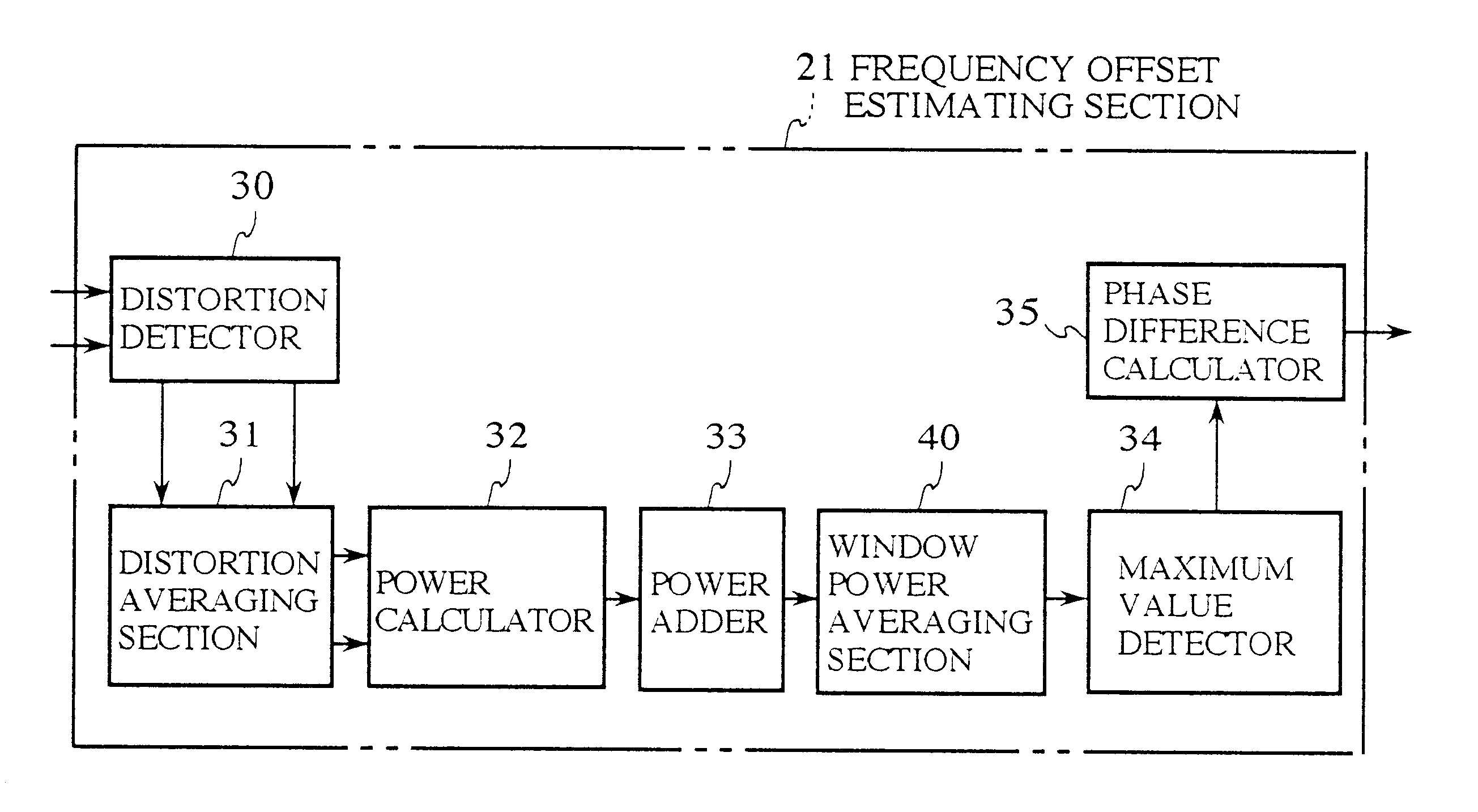
FIG. 8 is a block diagram showing a configuration of the frequency offset estimating section 21 installed in the automatic frequency controller of an embodiment 2 in accordance with the present invention. In other words, FIG. 8 is a drawing to be put in the place of FIG. 3 in the foregoing embodiment 1.

In the foregoing embodiment 1, the maximum value E.sub.f (n.sub.MAX) is detected from among the window powers E.sub.f (n) which are each obtained by the one-time window power operation processing carried out by the power adder 33. On the other hand, the present embodiment 2 averages the window powers E.sub.f (n) between the received burst signals using a forgetting factor .lambda. to improve the estimation accuracy of the frequency offset.

More specifically, the frequency offset estimating section 21 comprises a window power averaging section 40 which is disposed between the power adder 33 and the maximum value detector 34. The window power averaging section 40 is supplied with the win...

embodiment 3

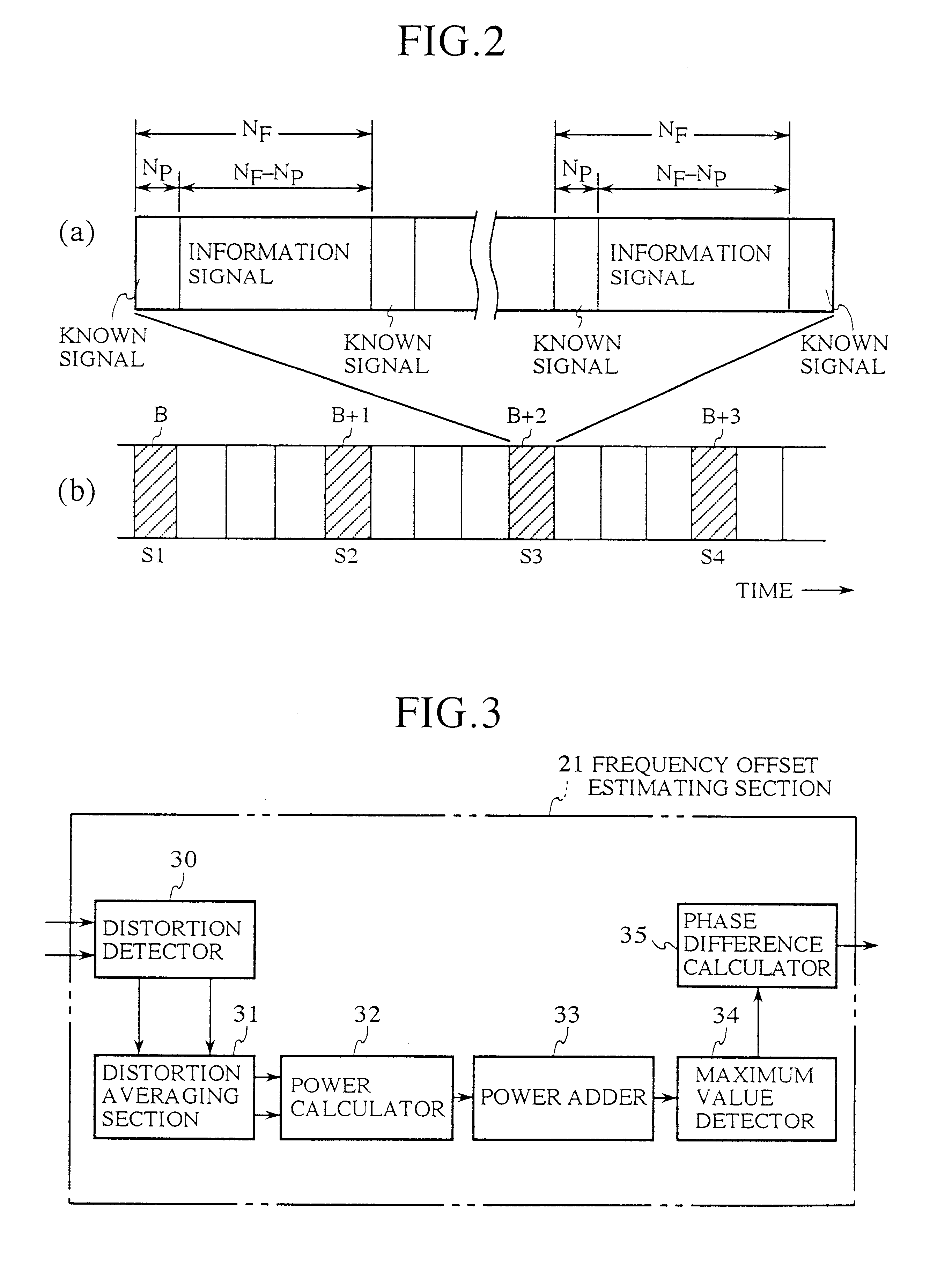
FIG. 9 is a block diagram showing a configuration of the frequency offset estimating section 21 installed in the automatic frequency controller of an embodiment 3 in accordance with the present invention. In other words, FIG. 9 is a drawing to be put in the place of FIG. 3 in the foregoing embodiment 1.

In the foregoing embodiment 2, the estimation accuracy of the frequency offset is improved by eliminating the effect of noise by averaging the window powers E.sub.f (n). Improving the estimation accuracy of the frequency offset by eliminating the effect of the noise can also be achieved by averaging the signal powers P.sub.f (n). Thus, the present embodiment 3 averages the signal powers P.sub.f (n) between the received burst signals to eliminate the effect of the noise, thereby improving the estimation accuracy of the frequency offset.

More specifically, the frequency offset estimating section 21 comprises a signal power averaging section 45 which is disposed between the power calculat...


PUM


Abstract

An automatic frequency controller includes a frequency offset estimating section that calculates phase distortion quantities and the average thereof from known signals contained in a received signal. The frequency offset estimating section obtains, from the average distortion quantity, signal powers corresponding to a plurality of candidate frequency offsets set at frequency offset estimation accuracy intervals in a frequency offset estimation range. The frequency offset estimating section looks at the signal powers through a frequency window with a frequency width corresponding to a transmission path state. This makes it possible to maximize the signal power of a frequency of a radio wave or radio waves corresponding to the transmission path state, and to place the radio wave or radio waves corresponding to the transmission path state as a frequency controlled object. This can improve demodulation accuracy. Fine adjustment of the candidate frequency offsets can improve the estimation accuracy of the frequency offset without changing the frequency offset estimation range.

Description

1. Field of the InventionThe present invention relates to an automatic frequency controller applied to digital demodulation processing in satellite communications, mobile satellite communications and mobile land communications, and a demodulator unit for demodulating a signal whose frequency is controlled by the automatic frequency controller.2. Description of Related ArtRecently, intensive researches of digital modulation and demodulation have been conducted in the field of the satellite communications, mobile satellite communications and mobile land communications. In the environment of mobile communications, in particular, communication signals undergo fading. Hence, various demodulation schemes have been proposed which can achieve stable operation in such a fading environment.A scheme which has attracted attention makes absolute coherent detection possible even under a fading environment by estimating and compensating for fading distortion using a known signal. To apply the sche...

Claims


Application Information

Patent Timeline
Patent Type & Authority Patents(United States)
IPC IPC(8): H03J7/02H03J7/04H04B17/00H04B7/005
CPCH03J7/04H04W52/225H04W52/16
Inventor ASAHARA, TAKASHIKOJIMA, TOSHIHARU
Owner MITSUBISHI ELECTRIC CORP
Why Eureka
Try Eureka