Non-scanning demodulation system based on optical fiber Fabry-Perot sensor

A Faber sensor and demodulation system technology, which is applied in the field of optical fiber sensing, can solve the problems of increasing the contrast of the effective demodulation signal, uneven distribution of signal light energy, and the influence of the contrast of the demodulation signal, so as to improve the effective demodulation signal. Contrast, increase the utilization of light intensity, avoid the effect of chromatic aberration

Inactive Publication Date: 2020-09-11
CHONGQING UNIV
View PDF1 Cites 7 Cited by
  • Summary
  • Abstract
  • Description
  • Claims
  • Application Information

AI Technical Summary

Problems solved by technology

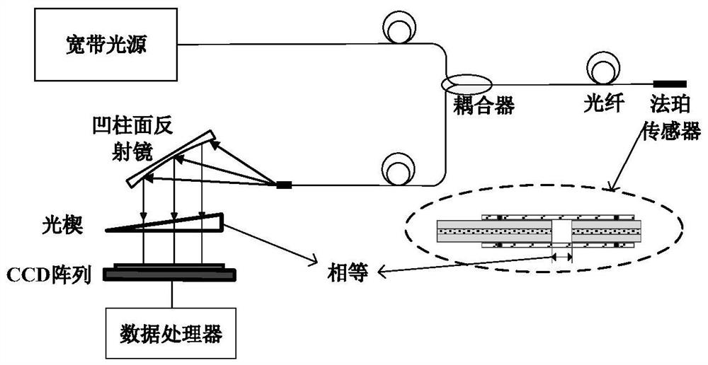
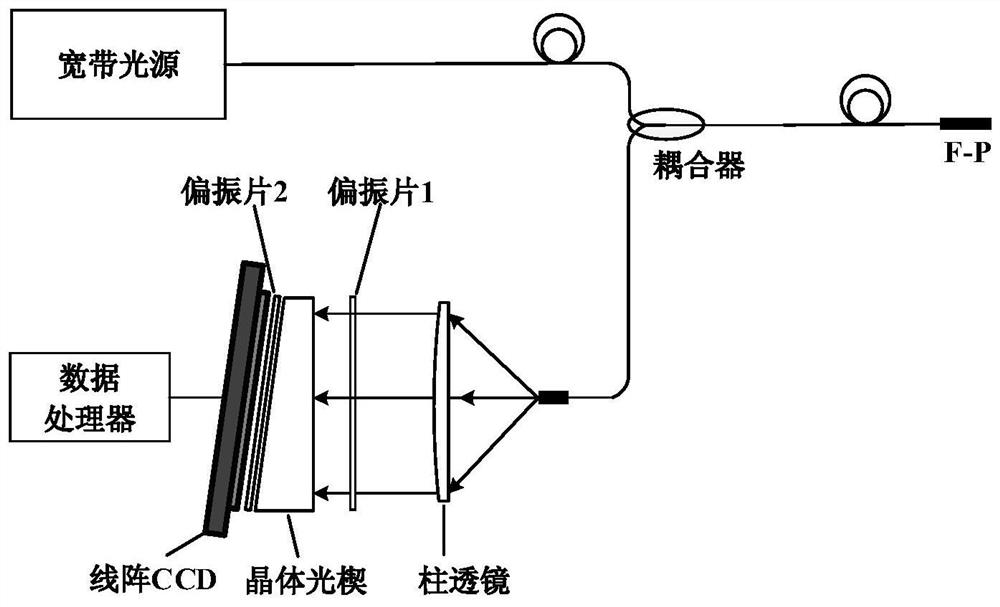
[0006] The above two systems use optical wedges to realize hardware-related demodulation, without moving parts, and have good stability; but in the demodulation module, there are only concave cylindrical mirrors or cylindrical lenses to shape the outgoing light of the sensor, and the incident light on the surface of the optical wedge The signal light energy distribution is uneven and the angle is not vertical, which has a certain impact on the contrast of the demodulated signal. The specific problems are:
[0009] To sum up, for the demodulation system, the incident light whose angle is perpendicular to the surface of the optical wedge can generate interference fringes on the surface of the optical wedge, which increases the effective contrast of the demodulated signal, while the light whose incident angle is not perpendicular to the optical wedge is received by the CCD , will only increase the DC component in the demodulated signal, that is, the noise floor, and will not help the cavity length demodulation

Method used


Image

  • Non-scanning demodulation system based on optical fiber Fabry-Perot sensor
  • Non-scanning demodulation system based on optical fiber Fabry-Perot sensor
  • Non-scanning demodulation system based on optical fiber Fabry-Perot sensor

Examples


Embodiment Construction

[0040] Hereinafter, the preferred embodiments of the present invention will be described in detail with reference to the accompanying drawings.

[0041] Such as Figure 4 As shown, the non-scanning demodulation system based on the optical fiber Fabry-Perot sensor of the present invention includes: a positive lens, a first free-form surface mirror, a second free-form surface mirror, an optical wedge, a plano-convex cylindrical lens, and a linear array CCD, data processor, optical fiber Fabry Perot sensor and coupler;

[0042] The positive lens is used to receive the light with cavity length information obtained from the optical fiber Fabry-Perot sensor, the light is emitted to the positive lens through the optical fiber, and the light is diverged into parallel light; the first free-form surface mirror is used to receive the positive lens The divergent parallel light is converted into flat-top light; the second free-form surface mirror is used to collimate the exit direction of the f...


PUM


Abstract

The invention relates to a non-scanning demodulation system based on an optical fiber Fabry-Perot sensor, whichbelongs to the technical field of optical fiber sensing. The system comprises a positivelens, a first free-form surface reflector, a second free-form surface reflector, an optical wedge, a plano-convex cylindrical lens, a linear array CCD and a data processor. The positive lens is used for receiving light with cavity length information obtained from the optical fiber Fabry-Perot sensor, and the light is emitted to the positive lens through the optical fiber and is diffused into parallel light; the first free-form surface reflector is used for receiving the parallel light diverged by the positive lens and converting the parallel light into flat-topped light; the second free-form surface reflector is used for collimating the emergent direction of the flat-topped light to ensure that the signal light incident to the optical wedge is perpendicular to the surface of the second free-form surface reflector; the plano-convex cylindrical lens is used for converting the rectangular light spot transmitted by the optical wedge into one-dimensional linear light; and the linear array CCD is used for detecting the one-dimensional linear light passing through the plano-convex cylindrical lens and outputting a voltage signal. The signal contrast can be effectively demodulated, and thedemodulation precision of a demodulation system can be improved.

Description

Technical field [0001] The invention belongs to the technical field of optical fiber sensing, and relates to a non-scanning demodulation system based on an optical fiber Fabry Perot sensor. Background technique [0002] Optical Fiber Fabry-Perot Sensor (Optical Fiber Fabry-Perot Sensor, referred to as optical fiber Fabry-Perot sensor) is a mature technology and widely used interference optical fiber sensor. It has the advantages of simple structure, good stability, small size, light weight, high sensitivity, and strong anti-electromagnetic interference ability. It is widely used in bridge structure health monitoring, civil engineering, large-scale civil building safety monitoring and other fields. [0003] The core of the optical fiber Fabry-Perot sensor is the fiber-optic Fabry-Perot cavity, which is to fix two lengths of optical fiber in the capillary, and ensure that the two ends are flat and parallel to each other, thereby forming a microcavity with a cavity length of L. figure...

Claims


Application Information

Patent Timeline
Patent Type & Authority Applications(China)
IPC IPC(8): G01D5/353
CPCG01D5/35312
Inventor 雷小华邓益俊陈伟民刘显明
Owner CHONGQING UNIV
Why Eureka
Try Eureka