Light module

a technology of light beams and modules, applied in the field of light beams, can solve the problems of significant material expenditure, the allocation of exhaust heat of semiconductor light sources, etc., and achieve the effect of preventing color aberration and more homogeneous light beam distribution

Active Publication Date: 2014-04-17
AUTOMOTIVE LIGHTING REUTLINGEN GMBH
View PDF17 Cites 12 Cited by
  • Summary
  • Abstract
  • Description
  • Claims
  • Application Information

AI Technical Summary

Benefits of technology

[0046]Another embodiment of the invention includes the secondary lens element being designed as a cylindrical reflector. This is designed as a section or segment of a cylindrical hollow mirror or a cylindrical parabolic mirror. The cylindrical reflector exhibits, for example, a parabolic curvature in the sagittal plane, and is designed to be without a curvature in sections perpendicular, in particular, to the sagittal plane. Because a cylindrical reflector light can not only concentrate or bundle, but can also deflect through reflection, the main beam direction of the light module can be structurally dictated with the specified structure. Furthermore, it is possible to prevent color aberrations that sometimes occur with the lenses, for example, which can lead to undesired color edges in the light beam distribution of the light module. The cylindrical reflector can exhibit scattering structures and / or facets, in order to obtain a more homogenous light beam distribution. Drum-like scattering structures are conceivable, for example, the drum axes of which run parallel to the cylinder axis of the cylindrical reflector.

Problems solved by technology

Due to the two-step structure, projection systems normally require a large assembly space along the beam path.
This can lead to problems regarding the exhaust heat of the semiconductor light sources allocated to the respective light coupling surfaces, because these are disposed in close proximity to one another.
Furthermore, there is a significant expenditure in terms of materials.

Method used


Image

  • Light module
  • Light module
  • Light module

Examples


Embodiment Construction

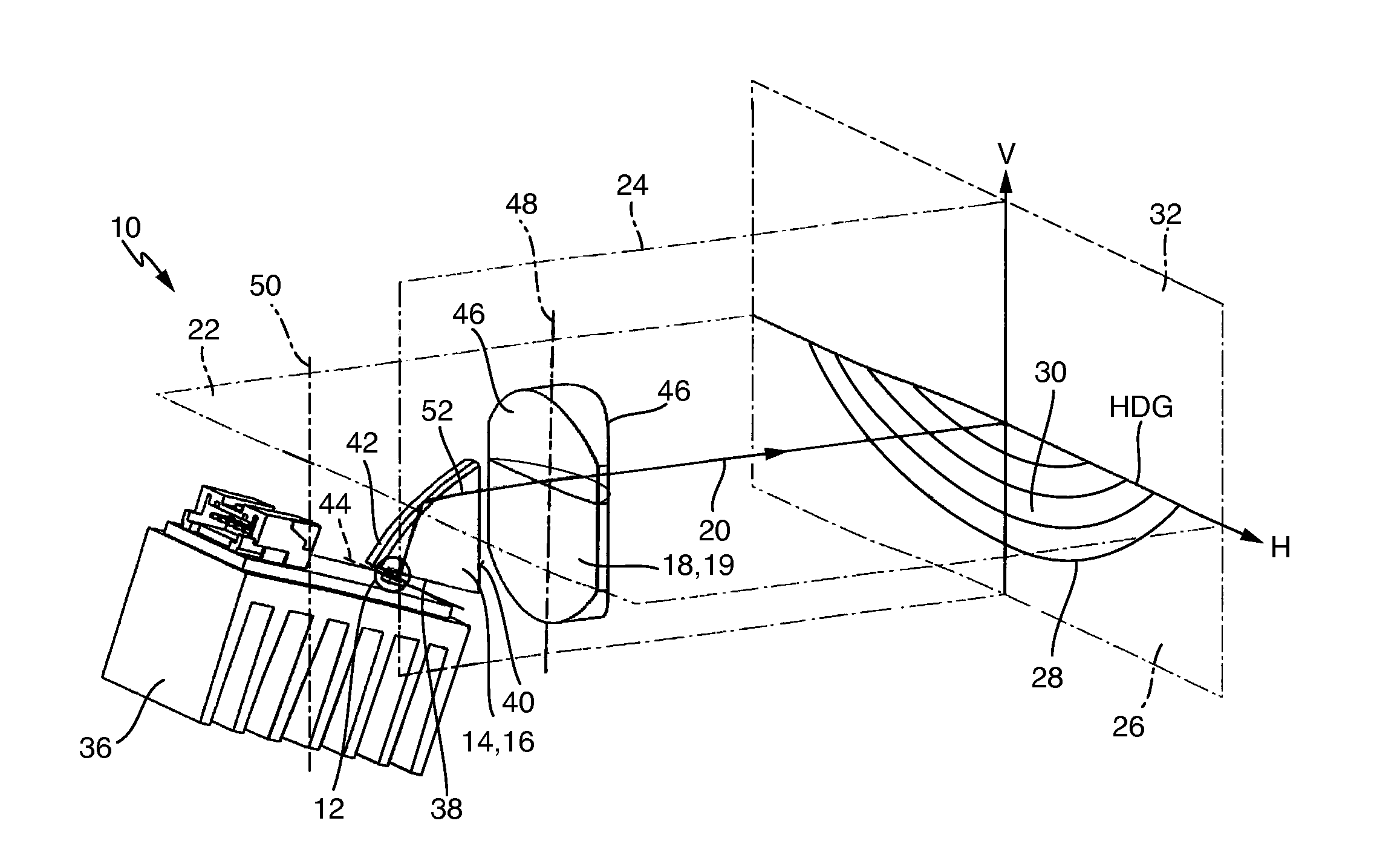
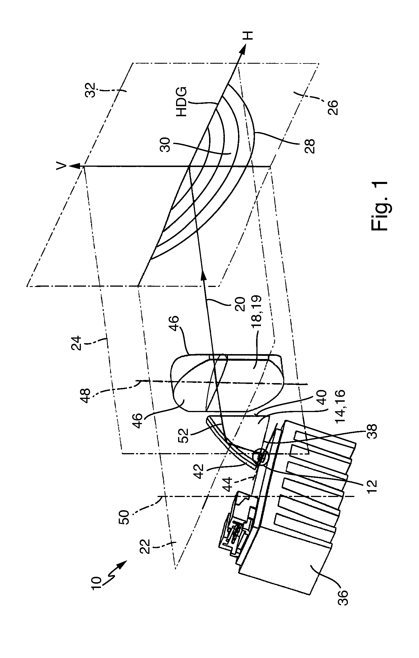
[0061]In the following description, identical or corresponding components are provided with the same reference symbols. Information regarding the spatial positions of various components shall be provided in the following based on various planes in space. In explanation of the planes, FIG. 1 shows details of a light module 10, wherein the design features shown can be used in all of the light modules according to the invention.

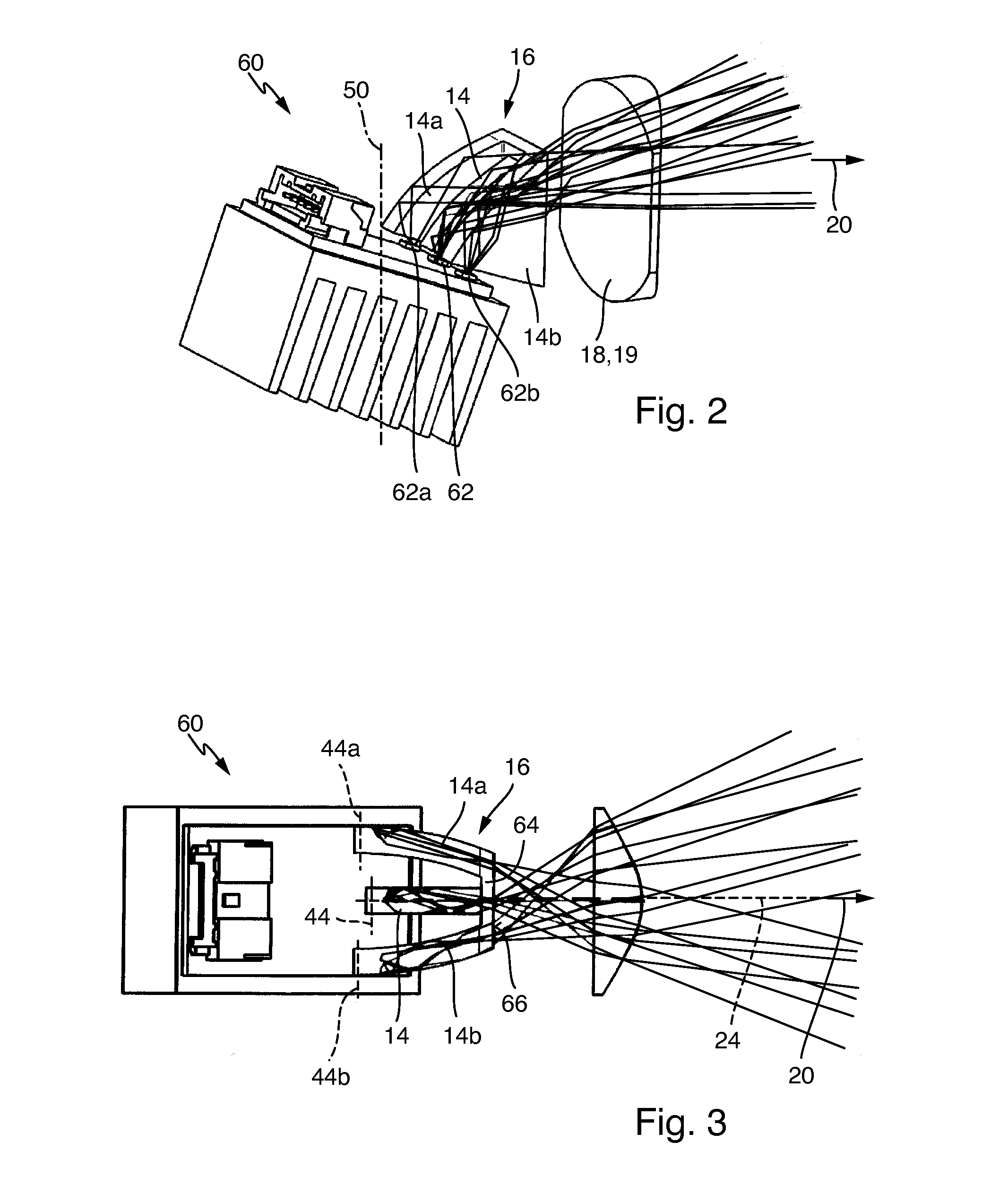
[0062]A semiconductor light source 12, a disk-like light conducting section 14, as part of a primary lens element, as well as a secondary lens element 18, designed as a cylindrical lens 19, are shown in FIG. 1. For the light module, a main beam direction 20 is defined, in which the light energy is emitted in the spatial center thereof. Furthermore, a sagittal plane 22 is defined, which spans the horizontal plane and the main beam direction 20 in the depicted example. Moreover, a meridional plane 24 is defined as that plane extending perpendicular to the sagittal...


PUM


Abstract

A light module, comprising numerous semiconductor light sources for emitting light, a primary lens element for concentrating the light emitted from the semiconductor light sources in section perpendicular to a sagittal plane of the light module, wherein the primary lens element exhibits numerous disk-like light conducting sections, extending in a plane perpendicular to the sagittal plane, wherein each light conducting section exhibits a light coupling surface and a light decoupling surface, and is designed for conducting light, subjected to a total reflection, from the light coupling surface to the light decoupling surface, wherein a semiconductor light source is allocated to each light conducting section such that light form the semiconductor light source can be coupled with the respective light coupling surface in the light conducting section.

Description

CROSS-REFERENCE TO RELATED APPLICATION[0001]This application is based upon and claims priority to German Patent Application 10 2012 218 684.0 filed on Oct. 12, 2012.BACKGROUND OF INVENTION[0002]1. Field of Invention[0003]The invention relates to a light module for motor vehicle headlights.[0004]2. Description of the Related Art[0005]In the present context, a light module is understood to be the actual light emitting unit that delivers the desired light beam distribution. This light module can be installed in a motor vehicle headlight, e.g. incorporated in a headlight housing. Depending on the field of application, the light beam distribution should exhibit certain, frequently government regulated, characteristic intensity distributions.[0006]On the one hand, it is of interest to generate a dimmed light distribution, distinguished by a light / dark border that is substantially horizontal in sections. This light distribution exhibits a dark region vertically above the border, and a ligh...

Claims


Application Information

Patent Timeline
Patent Type & Authority Applications(United States)
IPC IPC(8): F21S8/10F21W107/10
CPCF21S48/12F21S41/147F21S41/24F21S41/26F21S41/275F21S41/27F21S41/321F21S41/322F21S41/323F21S41/60F21S41/663F21S45/47F21S41/365F21S41/20
Inventor BRENDLE, MATTHIAS
Owner AUTOMOTIVE LIGHTING REUTLINGEN GMBH
Why Eureka
Try Eureka