Demodulator and communication device using the same

a communication device and demodulator technology, applied in the field of demodulators, can solve the problems of increasing the circuit scale and current consumption of the demodulator as a whole, the demodulation sensitivity of the fm the demodulation sensitivity of the demodulation circuit is affected, so as to achieve the effect of stabilizing the demodulation sensitivity of the demodulation circui

Inactive Publication Date: 2005-02-01
SHARP KK
View PDF6 Cites 7 Cited by
  • Summary
  • Abstract
  • Description
  • Claims
  • Application Information

AI Technical Summary

Benefits of technology

It is an object of the present invention to provide a demodulator which can stabilize the demodulation sensitivity of a demodulation circuit with restraining increases in circuit scale and current consumption, and adjust dispersions in the demodulation sensitivities of the respective ICs due to relative errors of a resistance value of a resistor and a capacity value of a condenser inside an IC, and to provide a communication device provided with the demodulator.
Consequently, control on the characteristic of the demodulation circuit, for example, stabilization of demodulation sensitivity, is carried out based on the demodulated signal obtained when the reference signal is inputted to the demodulation circuit which is the subject of the control. Therefore, overall circuit scale of the demodulator can be reduced compared with a conventional case where the characteristic of the demodulation circuit is controlled by using the result in a circuit for characteristic control which is provided aside from the demodulation circuit, resulting in restraining a current consumed in the circuit.
Consequently, the demodulation sensitivity can be stabilized by stabilizing the control on the frequency characteristic of the demodulation circuit based on the demodulated signal obtained when the reference signal is inputted to the demodulation circuit which is the subject of the control. Therefore, overall circuit scale of the demodulator can be reduced compared with a conventional case where the characteristic of the demodulation circuit is controlled by using the result in a circuit for characteristic control which is provided aside from the demodulation circuit, resulting in restraining a current consumed in the circuit.
In this case, demodulation sensitivity is automatically stabilized in the demodulator of the receiving section, and thus receiving accuracy and demodulation accuracy of the modulated signal can be improved.

Problems solved by technology

However, when the FM demodulation circuit and the filter circuit are integrated in the demodulator, absolute accuracies of a resistance value of a register, a capacity value of a condenser, etc. in this integrated circuit (hereinafter referred to as an IC) are not satisfactory, causing a deviation in demodulation sensitivity and frequency characteristic for each IC.
This arrangement causes increases in circuit scale and current consumption of the demodulator as a whole.
Besides, although a relative accuracy is satisfactory compared with an absolute accuracy in an identical IC, a dispersion occurs in the demodulation sensitivity of the FM demodulation circuit, due to relative errors in the resistance value of the resistor and the capacity value of the condenser inside the IC.

Method used


Image

  • Demodulator and communication device using the same
  • Demodulator and communication device using the same
  • Demodulator and communication device using the same

Examples


first embodiment

[First Embodiment]

The following description will explain one embodiment of the present invention. Incidentally, in the present embodiment, explanation will be given on a demodulator which uses a frequency modulated signal (FM signal) as a modulated signal and demodulates the FM signal.

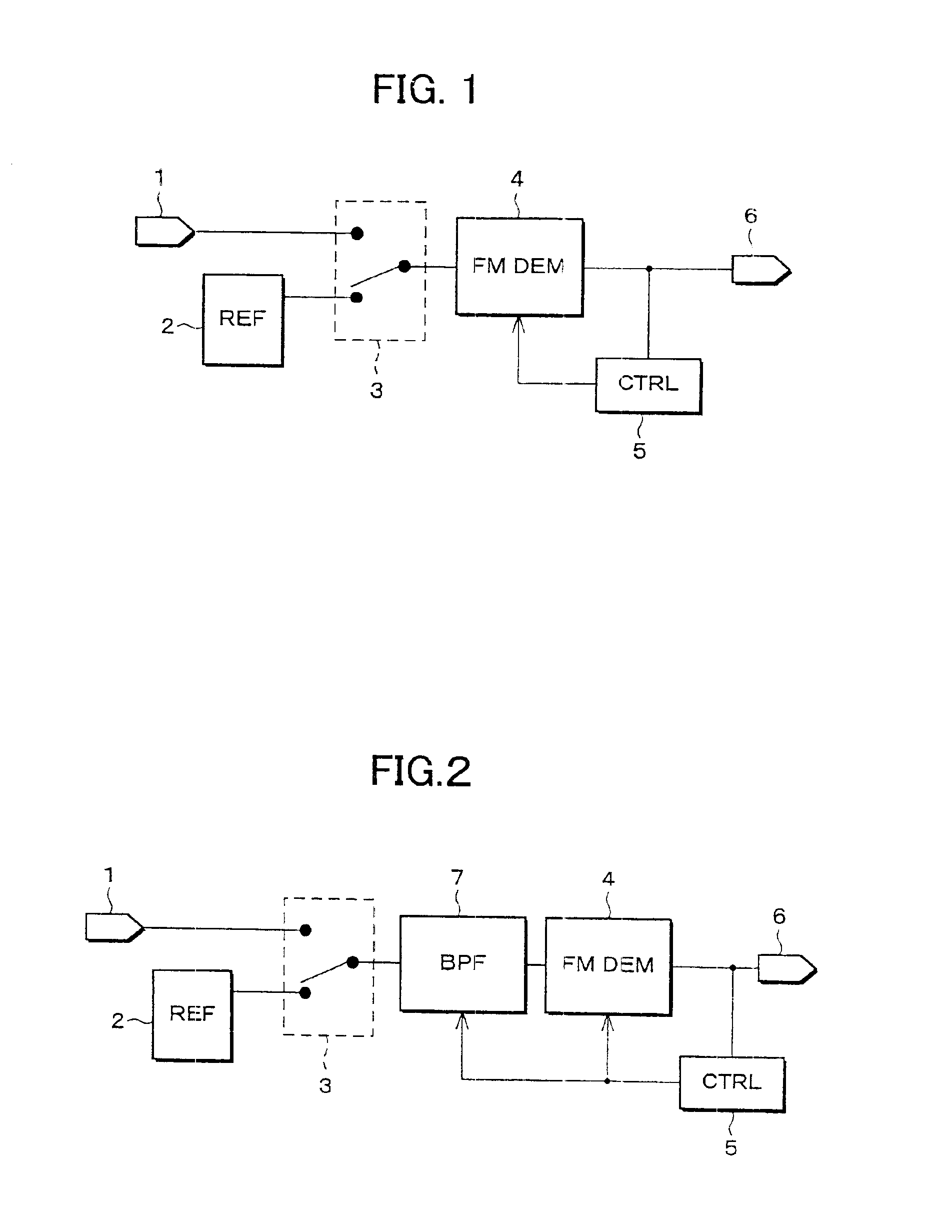
As shown in FIG. 1, the demodulator in accordance with the present embodiment is structured so as to include an input terminal 1 to which an FM signal is inputted; a reference signal generator (REF) 2 for generating a reference signal; an FM demodulation circuit (FM DEM) 4 for demodulating the inputted FM signal; a switch circuit 3 for switching between the FM signal from the input terminal 1 and the reference signal from the reference signal generator 2 to transmit either one of the signals to the FM demodulation circuit 4; an output terminal 6 for outputting a demodulated signal from the FM demodulation circuit 4; and a control circuit (CTRL) 5 for controlling a characteristic of the FM demodulation ...

second embodiment

[Second Embodiment]

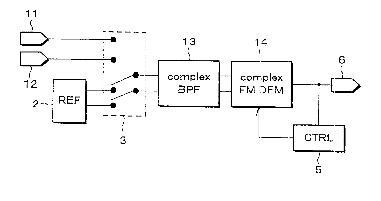
The following description will explain another embodiment of the present invention. Incidentally, in the present embodiment, explanation will be given on a demodulator which uses a frequency modulated complex signal and demodulates the complex signal. The members having the same structure (function) as those in the above-mentioned embodiment will be designated by the same reference numerals and their description will be omitted.

As shown in FIG. 6, in the demodulator in accordance with the present embodiment, the reference signal generator (REF) 2 for generating a reference signal, the switch circuit 3 for switching between the FM signal from the input terminal 1 and the reference signal from the reference signal generator 2, and the output terminal 6 for outputting a demodulated signal are the same as those in the demodulator of the first embodiment shown in FIG. 1, and thus their description will be omitted.

The demodulator shown in FIG. 6 further includes input t...

third embodiment

[Third Embodiment]

The following description will explain still another embodiment of the present invention. Incidentally, in the present embodiment, explanation will be given on an example in which the demodulator shown in FIG. 5 in the first embodiment is applied to a wireless communication device which performs wireless communication as a communication device.

The wireless communication device in accordance with the present embodiment is structured so as to include a signal receiving section and a signal transmitting section.

As shown in FIG. 10, the foregoing receiving section includes an input terminal 50 to which a receiving signal is inputted, an amplifier 51 for amplifying the receiving signal, a mixer 52 for converting a frequency of the receiving signal, a local oscillator 53 for providing a local signal to the mixer 52, an A / D converter 54 for converting a demodulated analog signal outputted from the FM demodulation circuit 4 to a digital signal, a logic circuit 55 for proce...


PUM


Abstract

A demodulator includes a reference signal generator for generating a reference signal, an FM demodulation circuit for demodulating a modulated signal, and a control circuit for controlling demodulation sensitivity of the FM demodulation circuit. The control circuit controls the demodulation sensitivity of the FM demodulation circuit so that an output signal, obtained when the reference signal from the reference signal generator is inputted to the FM demodulation circuit, becomes a specified value. This structure can stabilize the demodulation sensitivity of the demodulation circuit while restraining increases in circuit scale and current consumption, and can adjust dispersions in the demodulation sensitivities of the respective ICs due to relative errors of a resistance value of a resistor and a capacity value of a condenser in an IC, the resistor and the condenser constituting the demodulator.

Description

FIELD OF THE INVENTIONThe present invention relates to a demodulator for demodulating a modulated signal, for example, a frequency modulated signal [FM (Frequency Modulation) signal], more particularly to a demodulator having a circuit for automatically adjusting demodulation sensitivity of a modulated signal, and a communication device provided with the demodulator.BACKGROUND OF THE INVENTIONGenerally, when using a demodulator demodulating a modulated signal, for example, a frequency modulated signal (hereinafter referred to as an FM signal), in a wireless communication device, an FM demodulation circuit and a filter circuit or a phase shifter are required. In addition, along with miniaturization of a device having a demodulator in recent years, such as a wireless communication device, the downsizing of the demodulator has been promoted.As a means to downsize the demodulator, it can be considered to integrate an FM demodulation circuit and a filter circuit. However, when the FM dem...

Claims


Application Information

Patent Timeline
Patent Type & Authority Patents(United States)
IPC IPC(8): H03D3/00H04B1/16H04B1/3822H04B1/40
CPCH03D3/002
Inventor AMANO, SHINJI
Owner SHARP KK
Why Eureka
Try Eureka