
Direct automatic frequency control method and apparatus

a frequency control and automatic technology, applied in the field of wireless communication, can solve the problems of increasing the cost of mobile terminals, consuming printed circuit board space, and many errors that change non-linearly, and achieve the effect of reducing errors

Inactive Publication Date: 2005-02-15
OPTIS WIRELESS TECH LLC
View PDF10 Cites 30 Cited by
  • Summary
  • Abstract
  • Description
  • Claims
  • Application Information

AI Technical Summary

Benefits of technology

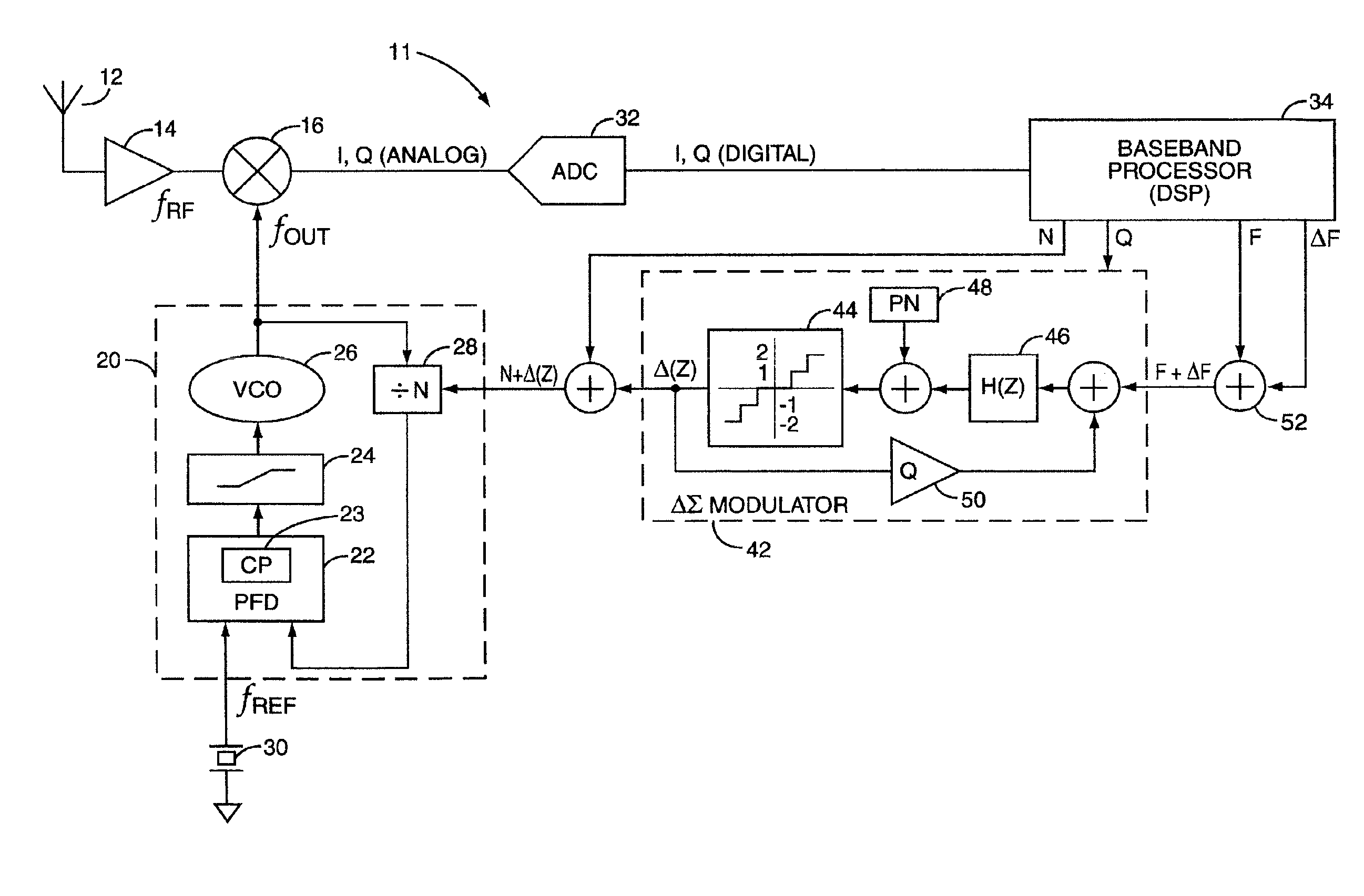
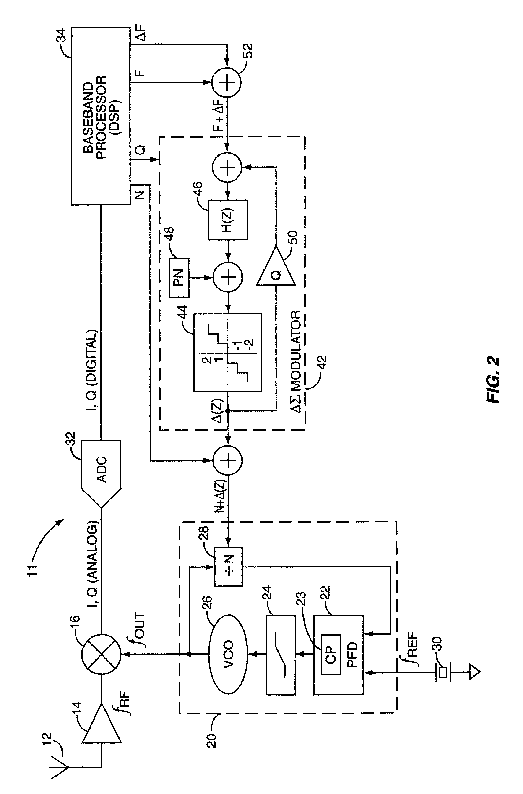
The present invention relates to a method of automatically controlling an output frequency. The phase difference between a reference frequency and a divided output frequency is detected. The output frequency is generated in response to the phase difference, and error in the output frequency is detected. The output frequency is divided by at least two distinct integer values over a specified duration, the integer values selected in response to the error in the output frequency, to generate the divided output frequency. In this manner, the output frequency is controlled to reduce the error.

Problems solved by technology

Each element in the XTAL oscillator tuning circuit introduces errors due to component tolerance, aging, reflow soldering effects, and the like; furthermore, many of these errors change non-linearly with temperature.
The XTAL oscillator tuning circuit components and DAC add cost to the mobile terminal, consume printed circuit board space, and decrease reliability by providing additional failure points.
The extensive characterization of the XTAL oscillator tuning circuit to create initial look-up table entries is time consuming and costly.
Finally, the dynamic adaptation of the look-up table entries consumes limited processing resources and adds complexity to the radio control software.

Method used


Image

  • Direct automatic frequency control method and apparatus
  • Direct automatic frequency control method and apparatus
  • Direct automatic frequency control method and apparatus

Examples


Embodiment Construction

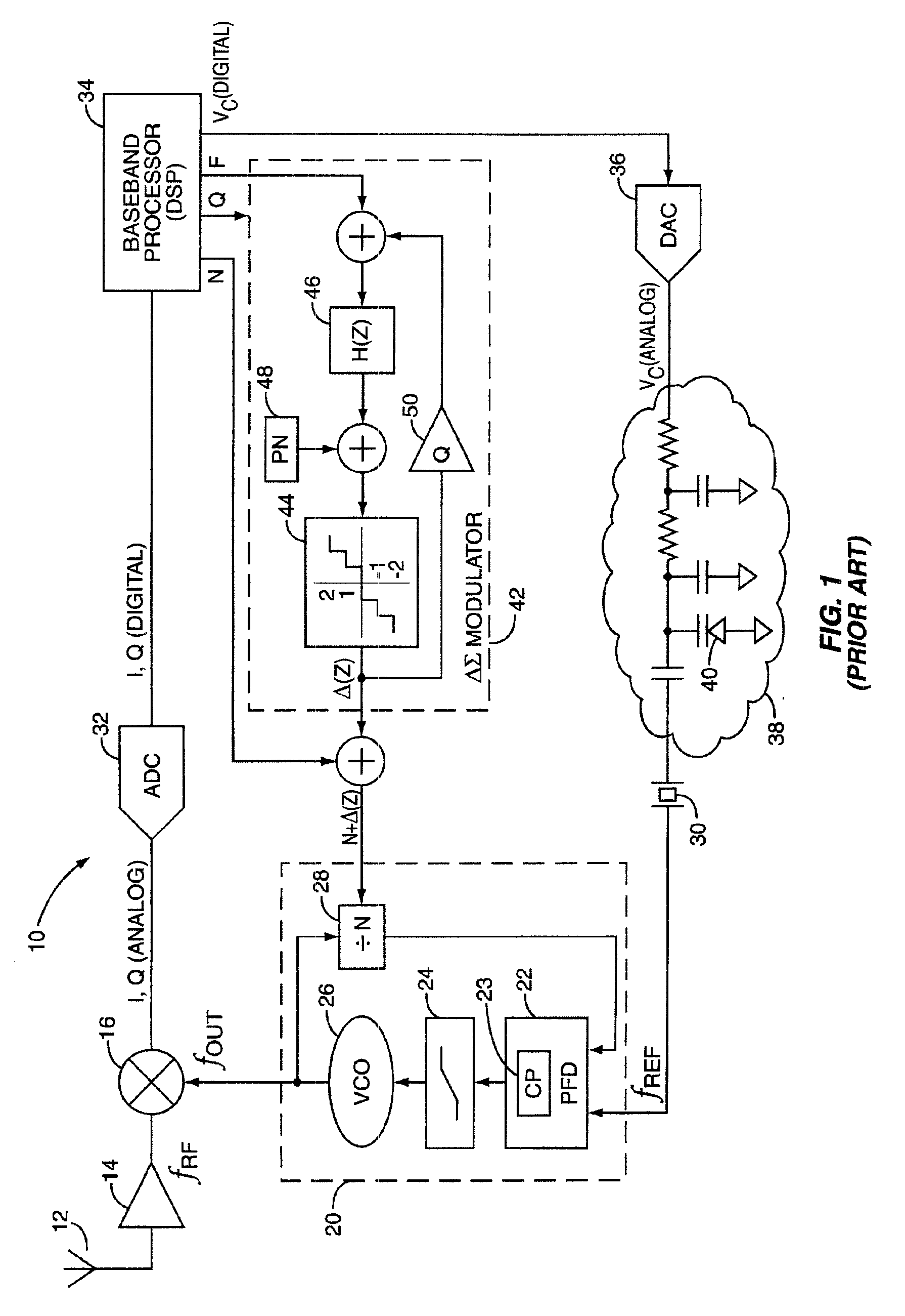
Modern mobile communication terminals use Phase Locked loop (PLL) frequency synthesizers to control the receive and transmit channel frequencies. The general architecture of a PLL-based Automatic Frequency Control (AFC) circuit for downconverting a received RF signal to baseband is depicted in FIG. 1, indicated generally at 10. A transmitted RF signal at frequency fRF is received at antenna 12, amplified by RF low-noise amplifier 14, and mixed with frequency fOUT at mixer 16 (multiple conversion (>1) hetrodyne receivers may include additional downconversion mixers). The frequency fOUT is generated by a Phase Locked loop 20, based on a reference frequency fREF generated by a crystal (XTAL) oscillator 30 and its associated control circuit 38. The mixer 16 outputs sum and difference components (fRF+fLO) and (fRF−fLO), which are digitized by Analog to Digital Converters (ADC) 32, and processed by a baseband processor 34. The baseband processor 34 detects and extracts information symbols...


PUM


Abstract

An Automatic Frequency Control (AFC) circuit for a mobile terminal employs a fractional-N Phase Locked Loop (PLL) to directly reduce errors in the synthesized frequency, such as due to component tolerances, temperature drift, and the like. The frequency error is detected by the average speed of rotation of the I,Q constellation. A corresponding offset is added to the tuning frequency selection word prior to encoding, such as in a ΔΣ modulator, to generate an effective non-integer PLL frequency division factor over a specified duration. The ΔΣ modulator may include dithering the different integer values by a pseudo-random number to minimize noise in the output frequency spectrum introduced by the fractional-N division. Component and parameter selection allow a high degree of resolution in frequency control of the fractional-N PLL. By directly controlling for the frequency error, a DAC and XTAL oscillator tuning circuit may be eliminated from the AFC circuit.

Description

BACKGROUND OF THE INVENTIONThe present invention relates generally to the field of wireless communications and specifically to an improved automatic frequency control circuit and method.Automatic frequency control (AFC) is a fundamental process for radio communication devices. AFC typically includes one or more phase-locked loop (PLL) circuit(s), which generate a high frequency periodic signal from a low frequency reference signal. AFC is used to perform a wide variety of tasks in wireless communication system components, such as frequency synthesis, AM and FM detection, frequency multiplication, tone decoding, pulse synchronization of signals from noisy sources, and the like, with high frequency accuracy.One conventional, representative application of AFC, described herein to explicate the present invention, is in conjunction with the downconversion of a received Radio Frequency (RF) signal, such as that produced by the transmitter at a base station, to the baseband frequency in a ...

Claims


Application Information

Patent Timeline
Patent Type & Authority Patents(United States)
IPC IPC(8): H03J7/02H03L7/197H03J7/06H03L7/16
CPCH03L7/1976H03J7/065
Inventor KLEMMER, NIKOLAUS
Owner OPTIS WIRELESS TECH LLC
Learn More