Automatic frequency control communication system

a communication system and frequency control technology, applied in multiplex communication, pulse technique, phase-modulated carrier systems, etc., can solve the problems of reduced bit error rate, increased power consumption, and reduced throughpu

Inactive Publication Date: 2002-09-24
MITSUBISHI ELECTRIC CORP
View PDF21 Cites 32 Cited by
  • Summary
  • Abstract
  • Description
  • Claims
  • Application Information

AI Technical Summary

Problems solved by technology

It is undesirable as it degrades throughput.
Thus, it is not desirable as an extended circuitry is required, which results in increased power consumption.
If the frequency offset exceeds the pull-in range, or when the frequency error vari

Method used


Image

  • Automatic frequency control communication system
  • Automatic frequency control communication system
  • Automatic frequency control communication system

Examples


embodiment 1

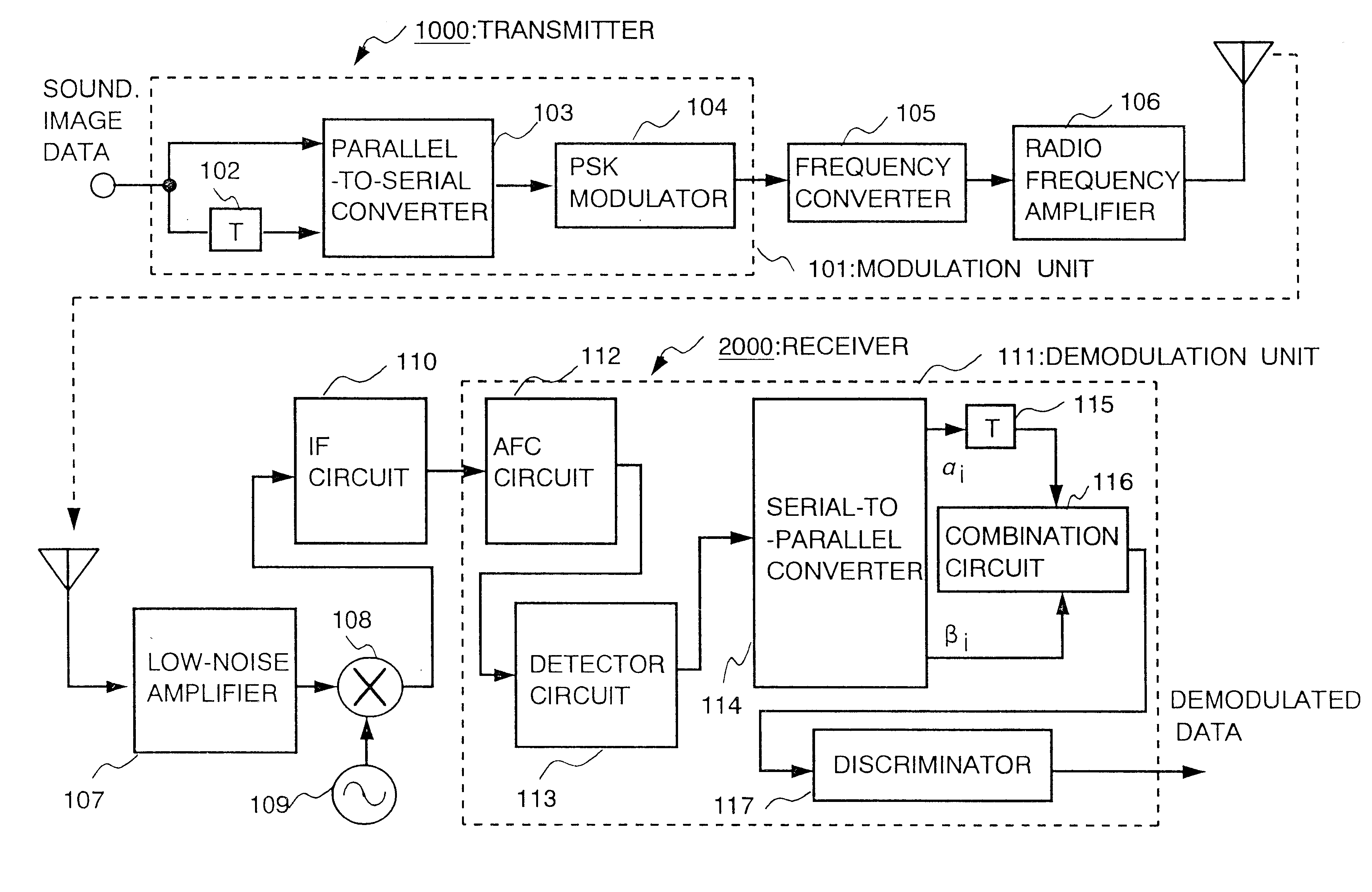
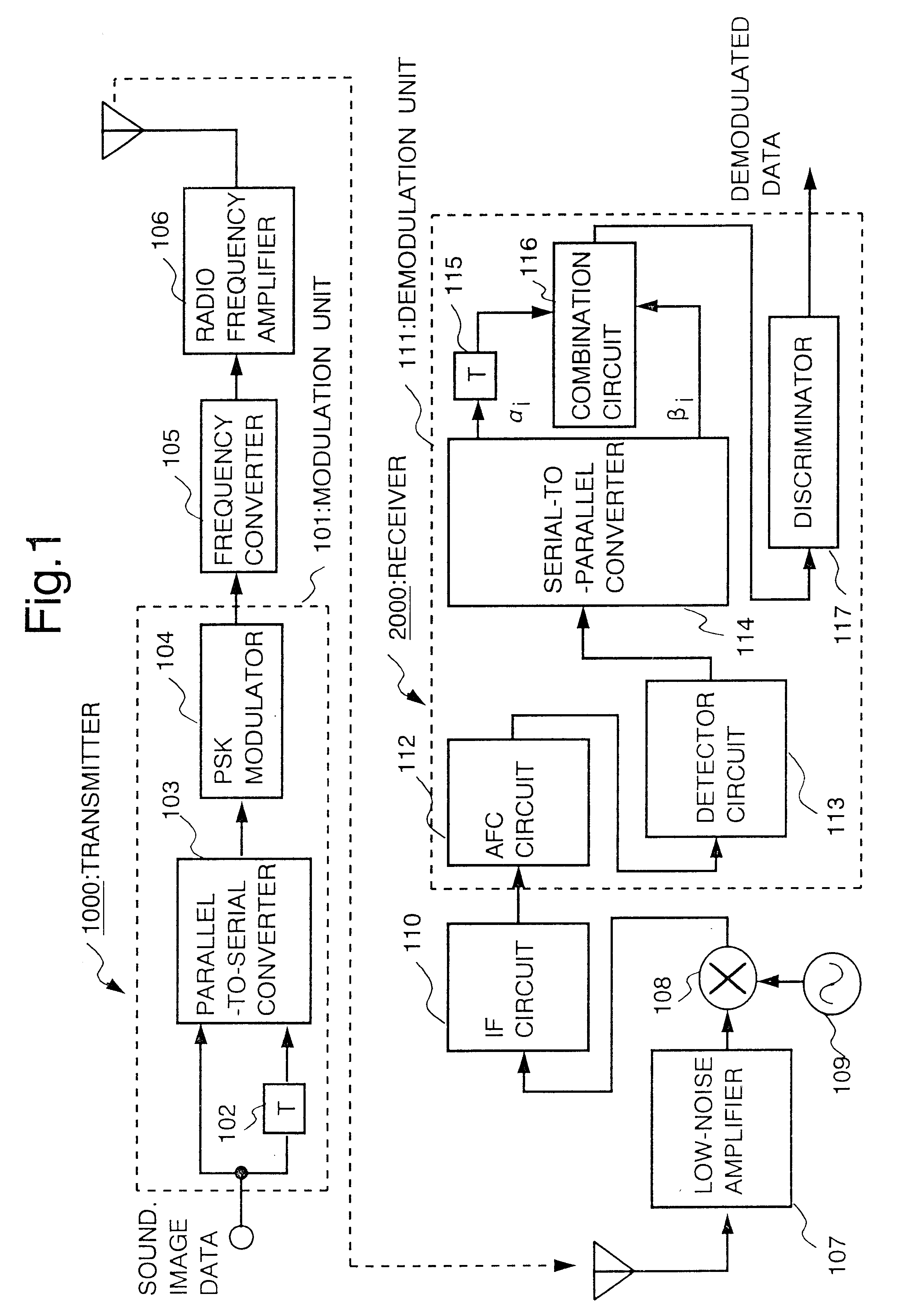
Embodiment 1 will be set forth below with reference to figures. FIG. 1 shows the configuration of a communication system of Embodiment 1. In FIG. 1, a modulation unit 101 of a transmitter 1000, delay units 102 and 115 having the delay time equivalent to the N-bit data time T, a parallel-to-serial converter 103, a Phase Shift Keying (PSK) modulator 104, a frequency converter 105, a radio-frequency amplifier 106, a low-noise amplifier 107 of receiver 2000, a mixer 108, an oscillator 109, an Intermediate Frequency (IF) circuit 110, a demodulation unit 111 of the receiver, an Automatic Frequency Control (AFC) circuit 112, a detector circuit 113, a serial-to-parallel converter 114, a combination circuit 116 and a determinator 117 are illustrated.

Next, the operation is explained. In FIG. 1, data such as sound, image, etc., is converted into digital signal by a sound coder(not shown), and so on, to make a data sequence to be transmitted. The data sequence to be transmitted is input into mo...

embodiment 2

Although combination circuit 116 of Embodiment 1 is configured to perform equal gain combination, this embodiment describes the maximum ratio combination.

FIG. 8 shows a configuration example of combination circuit 116 for maximum ratio combination. In FIG. 8, absolute value detectors 801 and 802, multipliers 803 and 804, and a vector adder 805 are shown. {.alpha..sub.i-N } and {.beta..sub.i } input into combination circuit 116 are input into absolute value detectors 801 and 802, respectively, so as to detect the absolute values .vertline..alpha..sub.i-N.vertline., .vertline..beta..sub.i.vertline.. The detected .vertline..alpha..sub.i-N.vertline. and .vertline..beta..sub.i.vertline. are multiplied by {.alpha..sub.i-N } and {.beta..sub.i } by multipliers 803 and 804, respectively, to be weighted in accordance with the SN ratio, and input into vector adder 805 to be added.

FIG. 9 is a baseband signal diagram for explaining the maximum ratio combination. In FIG. 9, if .vertline..alpha..s...

embodiment 3

In the foregoing Embodiment 1, although phase rotator 401 is incorporated inside AFC circuit 112 to rotate the phase of the received baseband signal, this embodiment is configured in a manner that the signal for controlling the frequency, namely the frequency control signal, is fed from AFC circuit 112 back to intermediate frequency oscillator 303 of IF circuit 110, so that phase rotator 401 and integrator 408 of AFC circuit 112 are omitted.

The configuration of a communication system of Embodiment 3 is shown in FIG. 10. In FIG. 10, parts the same as FIG. 1 are given the same numbers and their explanation is omitted. In FIG. 10, the received signal received by the receiver is amplified by low-noise amplifier 107, and input into mixer 108. Mixer 108 mixes the received signal with the oscillation frequency close to the received RF frequency output from oscillator 109, and converts the received signal into the intermediate frequency (IF). The converted received IF signal is input into I...


PUM


Abstract

In a communication system using the time diversity transmission scheme, the communication system provided with the stable automatic frequency control circuit with the wide frequency pull-in range and under low CN ratio transmission is achieved by removing the modulation phase from the received data through the application of the data correlation of the time diversity. The frequency offset in the received signal is compensated as the phase rotator rotates the phase of the received signal, the phase converter converts the phase rotator output into a phase, the serial-to-parallel converter converts the phase converter outputs into serial-to-parallel sequence, the delay units gives a delay to the serial-to-parallel converter output, the phase adder adds the serial-to-parallel converter output to the delay unit output, the multiplier multiplies the phase adder output by a certain value, the integrator integrates the multiplier output, another integrator integrates the integrator output, and the phase rotator controls the phase of the received signal based on the other integrator output.

Description

This invention relates to the improvement of a receiver in the field of radio communications.DESCRIPTION OF THE RELATED ARTAutomatic Frequency Control (AFC) circuit using a pilot signal, an automatic frequency control circuit of a conventional automatic frequency control communication system, is set forth in "AUTOMATIC FREQUENCY CONTROL CIRCUIT" in Japanese Unexamined Patent Application No. HEI08-330910. The conventional art is outlined below.The configuration of a conventional AFC circuit is shown in FIG. 31, wherein, a frequency converter 3101, a pilot signal extraction circuit 3102, an arc tangent calculation circuit 3103, a phase-difference calculation circuit 3104, a linear approximation circuit 3105, a frequency-error calculation circuit 3106, a variable oscillator 3107, and a memory 3108 are illustrated.The operation is explained next. A digital radio communication system is generally not free from frequency offset in received signals due to the difference in oscillation freq...

Claims


Application Information

Patent Timeline
IPC IPC(8): H03J7/02H04L27/233H04B7/04H04B7/06H04L1/00H04L27/18H04B1/707H04B1/7087H04J13/00
CPCH03J7/02H04B7/06H04L1/0054H04L1/0059H04L1/08H04L27/2332
Inventor UCHIKI, TATSUYAKOJIMA, TOSHIHARUSANO, HIROYASUOKUBO, SEIJIMIYAKE, MAKOTO
Owner MITSUBISHI ELECTRIC CORP
Why Eureka
Try Eureka