Drier and method of controlling drying for the same

A dryer and drying technology, applied in dryers, household dryers, drying solid materials, etc., can solve problems such as increased manufacturing costs

Inactive Publication Date: 2006-04-05
LG ELECTRONICS INC
View PDF0 Cites 7 Cited by
  • Summary
  • Abstract
  • Description
  • Claims
  • Application Information

AI Technical Summary

Problems solved by technology

In this case, there is also a problem of increased manufacturing cost

Method used


Image

  • Drier and method of controlling drying for the same
  • Drier and method of controlling drying for the same
  • Drier and method of controlling drying for the same

Examples


Embodiment Construction

[0054] Preferred embodiments of the present invention will now be described in detail with reference to the embodiments shown in the accompanying drawings.

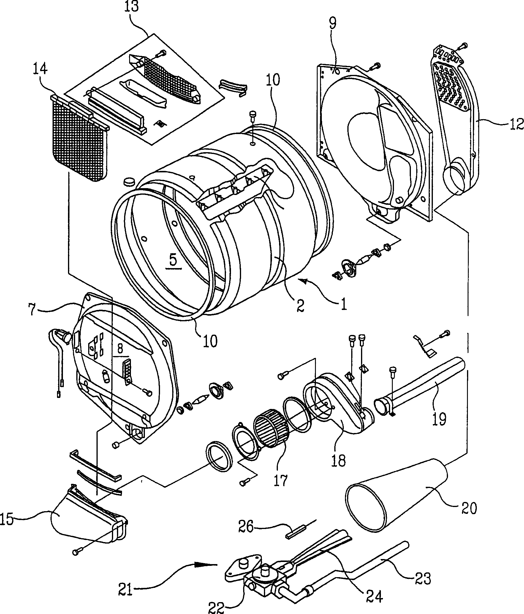
[0055] Figure 4 and 5 The structure of a dryer proposed according to the present invention is shown.

[0056] see Figure 4 and 5 , The dryer of the present invention has a housing 53 forming its outer cylinder. A front plate 41 is connected to the front end of the housing 53 to form the front of the dryer. The drum 44 is rotatably installed inside the housing 53 so that laundry can be loaded into the drum 44 and dried therein. The drum 44 is rotated by a drum drive belt 54 which is looped around the outer surface of the drum 44 .

[0057] A vent hole 43 is formed corresponding to the inner surface of the front plate 41 , which opens toward the inside of the drum 44 . The function of the exhaust hole 43 is to exhaust the air from the drum 44 . A lint filter 36 is provided at the entrance of the exhaust hole 43 to r...


PUM


Abstract

PURPOSE: A control method of a heater for a drier and an apparatus thereof are provided to control the heater safely by operating the heater in rotating a blower motor over the reference speed, and to improve the reliability by preventing breakage or damage with restricting wrong operation. CONSTITUTION: A heater control apparatus for a drier is composed of a blower forming flow of air circulating in a drum; a heater heating air to supply hot blast to the drum; a speed detecting unit(300) detecting rpm of the blower; a comparator(320) comparing rotational speed from the speed detecting unit with the normal speed of the blower, and outputting a signal for driving the heater; and a control unit controlling the drier and operating the heater by outputting the driving signal. The reliability is improved by operating the heater in applying the heater control signal to the heater driving unit from normal operation of the blower motor.

Description

[0001] This application is a divisional application of the No. 02803310.8 patent application for invention filed on October 25, 2002, entitled "dryer and drying control method thereof". technical field [0002] The present invention relates to a drier and a drying control method thereof, in particular to a drier and a drying control method capable of stopping the operation of a heater when the drier malfunctions and capable of controlling the amount of electric energy required for a drying operation. Background technique [0003] Fig. 1 is an exploded perspective view of main components of a general dryer. Referring to FIG. 1, a drum 1 is installed in a case (not shown) forming a housing of a dryer. The drum 1 is cylindrical with both ends open, a belt groove 2 is formed along the middle part of the outer periphery of the drum 1, and a belt (not shown) is wound along the belt groove, and the belt is driven by another driving source. A drying chamber 5 in which drying can ta...

Claims


Application Information

Patent Timeline
Patent Type & Authority Applications(China)
IPC IPC(8): D06F58/26D06F58/28F26B21/00
CPCY02B40/72F26B3/04F26B21/004F26B21/06F26B21/12
Inventor 梁在锡金相斗郑成海
Owner LG ELECTRONICS INC
Why Eureka
Try Eureka