Color filter and electro-optical device

An electro-optical device and color filter technology, which is applied in optics, optical filters, nonlinear optics, etc., can solve problems such as uneven distribution of liquid crystal layers, uneven surfaces of colored layers and barrier layers, etc.

Inactive Publication Date: 2006-04-05
KATEEVA
View PDF0 Cites 1 Cited by
  • Summary
  • Abstract
  • Description
  • Claims
  • Application Information

AI Technical Summary

Problems solved by technology

[0008] Furthermore, since the surfaces of the colored layer and the barrier layer are not necessarily flat, for example, when a protective layer is formed on the colored layer and the barrier layer and used as a color filter layer to form a liquid crystal display device, if the surface layer is not flat enough, the liquid crystal layer distribution may not be flat

Method used


Image

  • Color filter and electro-optical device
  • Color filter and electro-optical device
  • Color filter and electro-optical device

Examples


Embodiment Construction

[0033] Embodiments of the present invention will be described below with reference to the drawings.

[0034] (1. The structure of the color filter layer)

[0035] (1-1 First Embodiment)

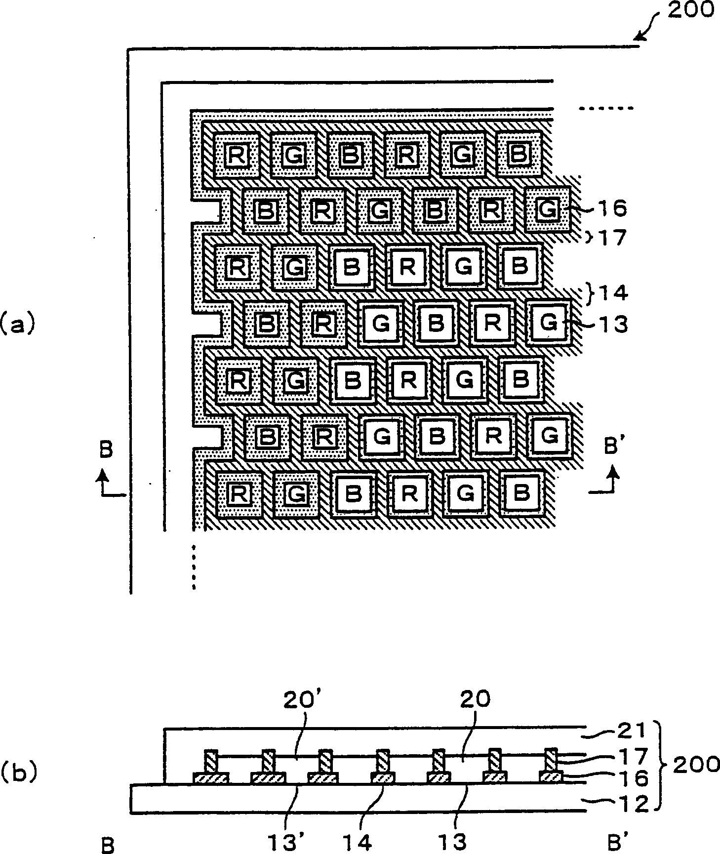
[0036] figure 1 It is a partially enlarged view of the color filter film layer in the first embodiment of the present invention. figure 1 (a) is a top view, figure 1 (b) is along figure 1 (a) Cross-sectional view along line B-B'.

[0037] Such as figure 1 As shown in (a), the color filter layer 200 is provided with pixels 13 arranged in a square array on the substrate 12 , and the boundaries between pixels are divided by partition walls 14 . One of red (R), green (G), and blue (B) inks is introduced into each pixel 13 . In this example, the arrangement of red, green, and blue is a mosaic arrangement, but other arrangements such as a stripe arrangement and a triangle arrangement may also be used.

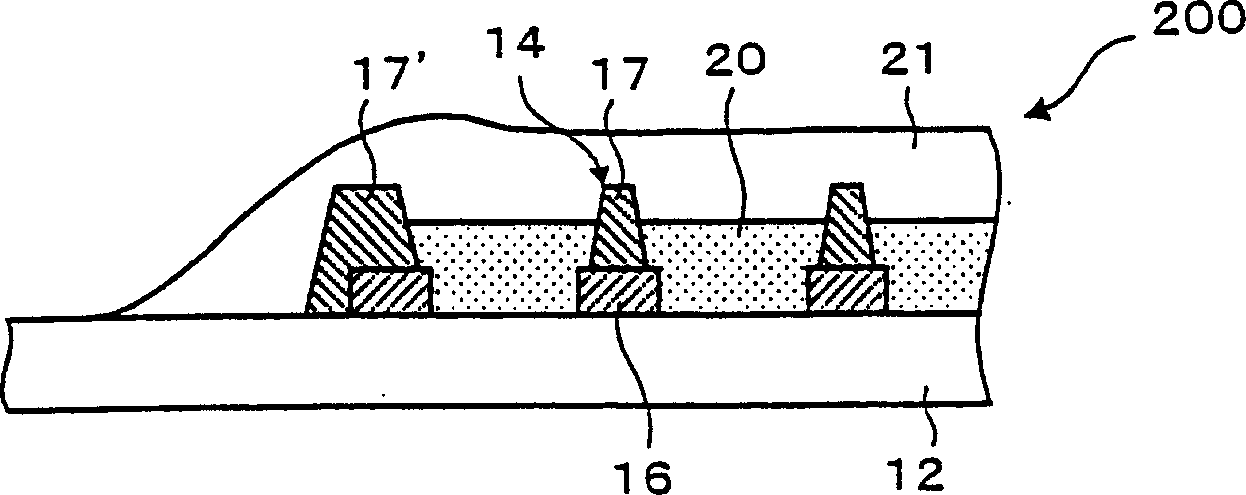
[0038] Such as figure 1 As shown in (b), the color filter layer 200 is provided with a ...


PUM

PropertyMeasurementUnit
thicknessaaaaaaaaaa
thicknessaaaaaaaaaa
thicknessaaaaaaaaaa

Abstract

The invention provides a color filter film layer and an electro-optical device, the color filter film layer is formed by the dividing of a room wall (14) formed on a substrate (12), and is a color filter film layer (200) of pixels (13) which consist of color elements formed by multicolor ink; and virtual pixels (131) are formed at the outside of the forming area of the pixels (13). The ink quantity of the ink given to every pixel (13) is almost the same with the ink quantity of the ink given to every virtual pixel (131). And a protection film (21) which is formed and covers the pixels (13) also covers the virtual pixels (131) at the same time.

Description

technical field [0001] The present invention relates to a color filter layer and an electro-optical device, in particular to a color filter layer and an electro-optic device capable of improving the uniformity of light transmission characteristics of each pixel among pixels. Background technique [0002] As a color filter layer used in display devices such as color liquid crystal display devices, after forming a square array of refraction parts and a partition wall with a barrier function on a transparent substrate, the coloring material is coated in the partition wall by the inkjet method. , obtained by drying and curing at a certain temperature. [0003] In the conventional method for producing a color filter layer described above, when the liquid is discharged, it is filled up to above the partition walls on the substrate. By drying and solidifying it at a certain temperature, its volume is reduced, so that the height of the colored layer is basically the same as that of...

Claims


Application Information

Patent Timeline
Patent Type & Authority Applications(China)
IPC IPC(8): G02F1/1335G02B5/20
Inventor 木口浩史有贺久片上悟
Owner KATEEVA
Why Eureka
Try Eureka