Air conditioner having indoor unit with automatic air filter celaning function

An air filter and indoor unit technology, which is applied in air conditioning systems, dispersed particle filtration, household appliances, etc., can solve the problems of increasing power consumption, increasing the resistance of inhaled air ventilation, and increasing the depth of the main body, so as to achieve reliability Dust suction, small attraction effect

Inactive Publication Date: 2006-04-05
PANASONIC CORP
View PDF2 Cites 3 Cited by
  • Summary
  • Abstract
  • Description
  • Claims
  • Application Information

AI Technical Summary

Problems solved by technology

[0009] However, in conventional air conditioners equipped with detachable air filters, depending on the frequency of use of the air conditioner, it is necessary to remove the air filter from the air conditioner and periodically perform maintenance such as washing with water or removing adhering dust with a vacuum cleaner. thus very troublesome
In addition, if periodic maintenance is not performed, there is a problem of reducing the performance of the air conditioner and increasing power consumption due to the accumulation of dust on the air filter to increase the ventilation resistance of the intake air.
[0010] Moreover, in the content disclosed in Patent Document 1, it is necessary to take out the electric vacuum cleaner every time the air filter is cleaned, connect its suction nozzle to the suction port of the brush cover, and move it on the air filter, which is very troublesome. and time-wasting issues
[0011] Moreover, in the case of the filter described in Patent Document 2, the dust attached to the air filter is automatically sucked, but since the sucked dust is collected by the separator, it is necessary to periodically remove and process the dust accumulated on the separator, which is not only troublesome. , and if you forget to deal with it, the dust adhering to the air filter will not be removed, and the ventilation resistance of the sucked air will increase, resulting in a decrease in the performance of the air conditioner and an increase in power consumption.
[0012] In addition, in the case of the air conditioner disclosed in Patent Document 3, a long brush having approximately the same length as the full width of the air filter is required, and the thickness of the air filter may be increased due to the band shape of the air filter, and the depth of the main body may become large. The problem

Method used


Image

  • Air conditioner having indoor unit with automatic air filter celaning function
  • Air conditioner having indoor unit with automatic air filter celaning function
  • Air conditioner having indoor unit with automatic air filter celaning function

Examples


Embodiment approach 1

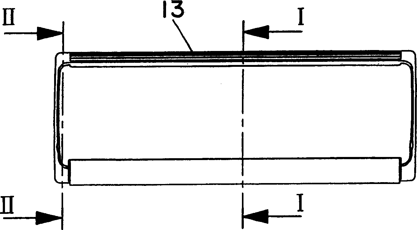
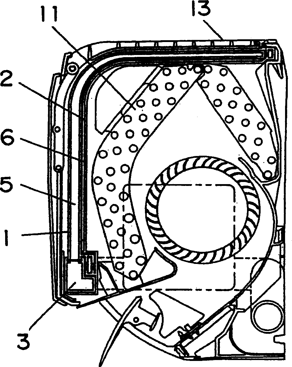
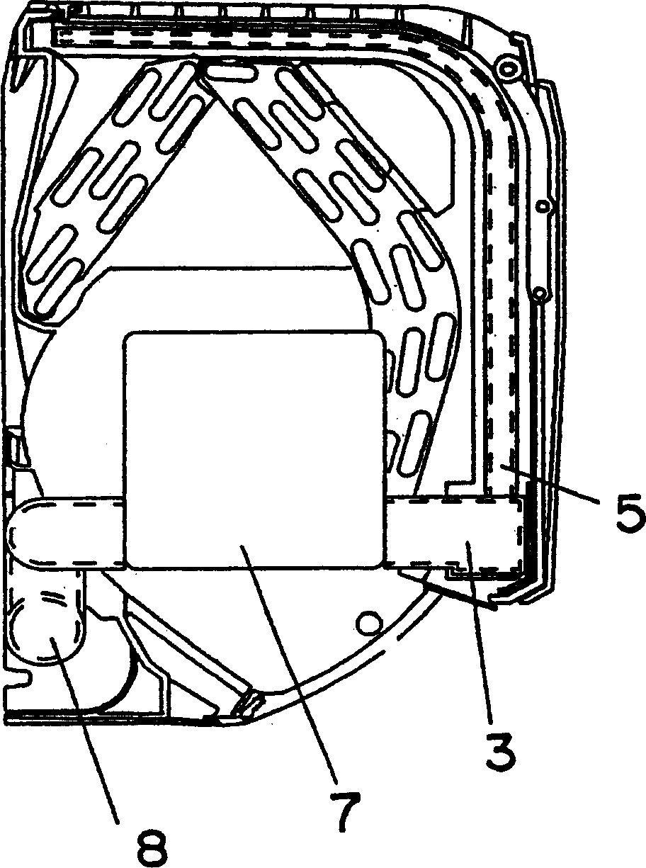
[0054] Figure 1 to Figure 3 An indoor unit showing an air conditioner according to Embodiment 1 of the present invention, figure 1 is the front view of the indoor unit, figure 2 as well as image 3 are along figure 1 Sectional views of line I-I and line II-II. and, Figure 4 as well as Figure 5 6A and 6B are a side view and a front view showing the appearance of a suction nozzle provided in the filter device.

[0055] In the inside of the indoor unit main body 13, there are housed: a heat exchanger 11; a fan 12 that sucks indoor air through the heat exchanger 11 and blows out air that has undergone heat exchange through the heat exchanger 11 to the room; The filter unit 1 on the upstream side of 11 sucks in air from a plurality of suction ports (not shown) formed by the operation of the fan 12, and the plurality of suction ports are formed from the front to the top of the main body 13, and are provided in the suction port and heat. Between the exchangers 11 the filte...

Embodiment approach 2

[0072] Figure 9 The filter device 1 shown in the indoor unit of the air conditioner according to Embodiment 2 of the present invention is different from the above-mentioned Embodiment 1 in that a vertically elongated baffle plate 14 is provided, and the elongated baffle plate 14 sandwiches Hold the air filter 6 and face the suction port 5a of the suction nozzle 5.

[0073] Such as Figure 10 as well as Figure 11 As shown, the upper and lower ends of the baffle 14 are respectively connected to the upper end 5 b and the lower end 5 c of the suction nozzle 5 , and are integrally formed with the suction nozzle 5 .

[0074] In this embodiment, by providing the shutter 14 at the position facing the nozzle suction port 5a on the inner surface side of the air filter 6, when the suction nozzle 5 moves in the left and right directions, the shutter 14 also moves together, and does not Since the remaining air is sucked from the suction port 5a, the dust adhering to the air filter 6 c...

Embodiment approach 3

[0080] Figure 14 to Figure 18 An indoor unit showing an air conditioner according to Embodiment 3 of the present invention, Figure 14 is the cross-sectional view of the indoor unit, Figure 15 It is a perspective view of the suction mechanism part of the filter device installed in the indoor unit, Figure 16 as well as Figure 17 is a partial sectional view of the suction mechanism seen from the back, Figure 18 It is an exploded perspective view of the suction nozzle.

[0081] Such as Figure 16 As shown, the suction duct 3 is formed in a cylindrical shape, and while one end is connected to a suction unit (not shown), the other end is closed. Openings 3 a are provided at equal intervals on the upper surface of the suction duct 3 , and opening and closing covers 16 are respectively attached to the openings 3 a. The opening and closing cover 16 normally closes the opening 3 a by a spring on the opening and closing cover 16 .

[0082] Through the fitting groove 5d, the ...


PUM


Abstract

An air conditioner, wherein a heat exchanger and a fan blowing air heat-exchanged in the heat exchanger into a room are stored in an indoor unit body, and an air filter is installed in the body on the upstream side of the heat exchanger. Also, the air conditioner comprises a sucking and exhausting device in which a suction nozzle having a suction port facing the air filter and sucking dirt adhered to the air filter is slidably fitted, communicating with the suction nozzle, and sucking and exhausting the dirt together with the air.

Description

technical field [0001] The present invention relates to an air conditioner provided with a function of automatically cleaning an air filter provided at an air suction port of an indoor unit. Background technique [0002] Conventional air conditioners such as Figure 28 as well as Figure 29 As shown, on the front of the heat exchanger 11, an air filter 6 for preventing dust from entering the main body 13 is provided, and the air filter 6 is detachably configured so that the attached dust can be cleaned by hand. [0003] Moreover, as an air conditioner that is easy to clean the air filter, it is provided with: a rotating brush; a brush cover that rotatably supports the rotating brush and covers the rotating brush; and a filter brush that is coaxial with the rotating brush. The suction nozzle of the electric vacuum cleaner is connected to the suction port provided on the brush cover, and moves on the air filter, and sucks while scraping off the dust accumulated on the air fil...

Claims


Application Information

Patent Timeline
Patent Type & Authority Applications(China)
IPC IPC(8): F24F1/00F24F1/02F24F3/16B01D46/10F24F13/28
Inventor 杉尾孝海老原正春清水昭彦米泽胜林正美清水努神野宁
Owner PANASONIC CORP
Why Eureka
Try Eureka