A splitter valve

A shunt valve and stream flow technology, which is applied in the air flow field of household cogeneration systems, can solve problems such as equipment damage, increased blade drive failure, etc.

Inactive Publication Date: 2006-04-19
MICROGEN ENERGY
View PDF1 Cites 10 Cited by
  • Summary
  • Abstract
  • Description
  • Claims
  • Application Information

AI Technical Summary

Problems solved by technology

This causes the motor to draw considerable current, and additionally higher loads increase the risk of blade drive failure
In these cases all flow will be diverted to this or another burner, which in worst case can cause damage to the equipment

Method used


Image

  • A splitter valve
  • A splitter valve
  • A splitter valve

Examples


Embodiment Construction

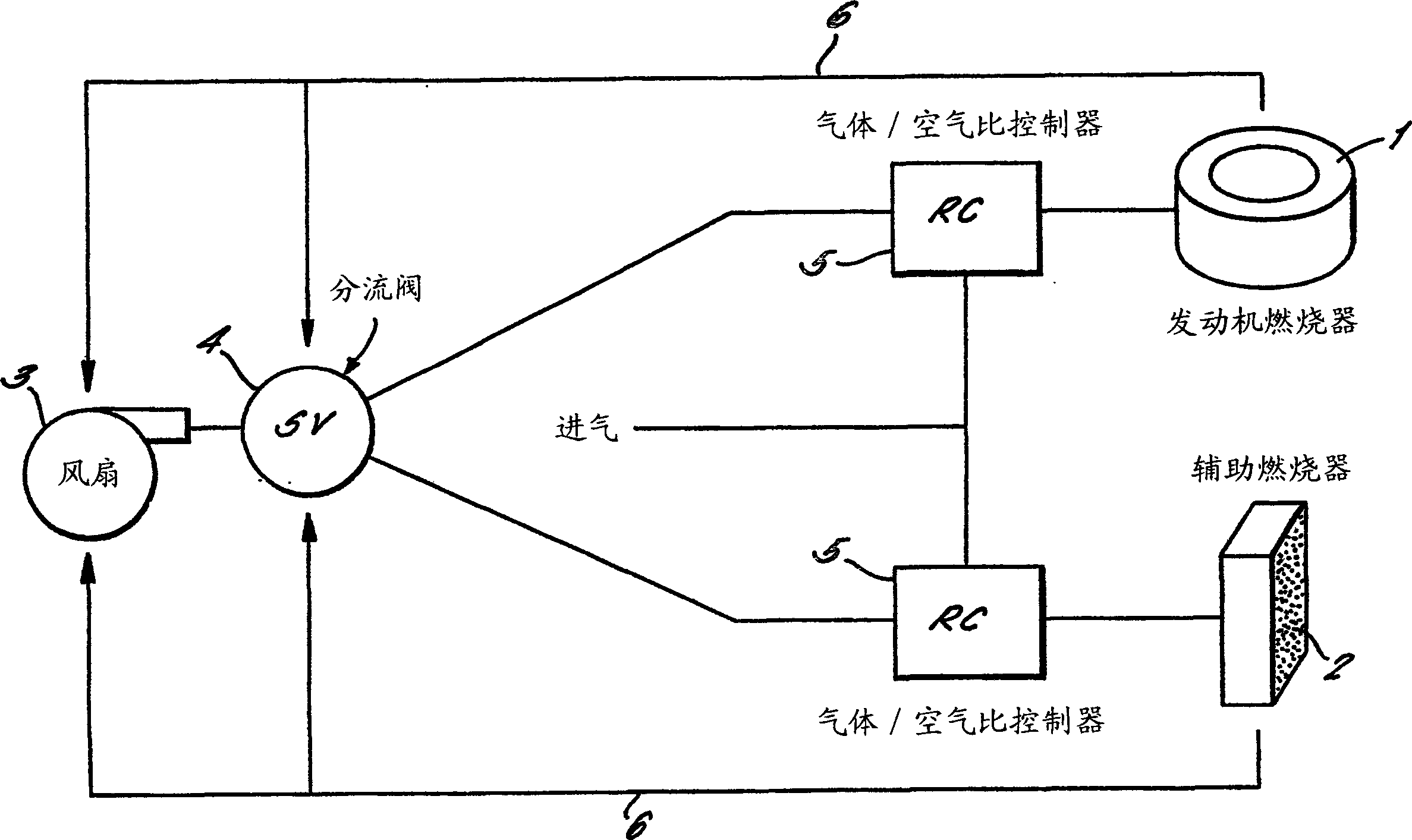
[0020] figure 1 A gas system for a domestic cogeneration system based on a linear free-piston Stirling engine is shown in .

[0021] The arrangement comprises two burners, Stirling engine burner 1 and auxiliary burner 2 . Stirling engine burners 1 are ignited according to domestic heat demand. This will also generate electricity as a by-product. However, in order to ensure sufficient capacity for all domestic heat loads, an auxiliary burner 2 is provided. Therefore, the two burners are adjusted according to the domestic heating needs. Air is supplied to both burners by a single fan 3 . This flow is diverted in a diverter valve 4 which will be described in more detail below. Fuel gas is added to each air stream under the control of the gas / air ratio controller 5 . The demand information of the burners 1 and 2 is fed back to the fan 3 and the diverter valve 4 along the control line 6 . The rotational speed of the fan 3 and the position of the diverter valve 4 are thus con...


PUM


Abstract

A splitter valve for splitting an inlet stream into a plurality of outlet streams. The valve comprising an inlet (31) and a plurality of outlets, one for each outlet stream. An outer sleeve (20) has a plurality of first outlet orifices (32, 33), one for each stream. An inner element (30) is moveably retained within the outer sleeve and has an inlet and a plurality of second outlet orifices (32, 33), one for each stream. The relative proportion of the inlet stream fed to each outlet is determined by the relative position of the inner element and outer sleeve. The first and second outlet orifices are shaped such that the flow through each outlet varies substantially linearly with the relative position of the inner element and outer sleeve.

Description

technical field [0001] The invention relates to a diverter valve for splitting an input flow into a plurality of output flows. [0002] In particular, the present invention relates to air flow for domestic combined heat and power (dchp) systems employing linear free piston Stirling engines. However, the invention is considered applicable to any application where a fluid stream is to be split into two or more streams. Background technique [0003] In a dchp system using a linear free piston Stirling engine, the engine fulfills some domestic thermoelectric needs. However, to supplement the heat output of the engine, auxiliary burners must be provided. In order to reduce the cost and space occupied by the equipment, as well as to reduce parasitic energy consumption, the air intake of the Stirling engine burner and the auxiliary co-burner is supplied by a single fan. The air from a single fan is then split into two streams (already mixed with fuel) supplied to the two burners...

Claims


Application Information

Patent Timeline
Patent Type & Authority Applications(China)
IPC IPC(8): F16K11/085F16K11/12F02G1/043F02G5/00
CPCY02T10/166F02G5/00F02G1/043Y02E20/14Y02T10/12
Inventor 斯蒂芬·迈克尔·哈斯基詹姆斯·爱德华·库珀
Owner MICROGEN ENERGY
Why Eureka
Try Eureka