Antenna for vehicle

A technology for antennas and vehicles, applied in the field of vehicle antennas, can solve problems such as low gain, antenna performance changes, and antenna performance effects, and achieve the effect of simple structure

Inactive Publication Date: 2006-04-19
CENT GLASS CO LTD
View PDF9 Cites 10 Cited by
  • Summary
  • Abstract
  • Description
  • Claims
  • Application Information

AI Technical Summary

Problems solved by technology

[0018] However, due to the antenna performance of any of the glass antennas for car phones or cellular phones shown in Patent Document 1 to Patent Document 3 and the glass antennas for TV broadcast wave reception shown in Patent Document 4 to Patent Document 6, it is easy to be placed by the position of the antenna Or the structure near the antenna placed in this way is affected, so the antenna element and the antenna setting position must be adjusted on a vehicle-by-vehicle basis
Furthermore, even if this adjustment is performed accordingly, the antenna performance will still change due to the influence of the human body
[0019] In addition, the glass antennas for car phones or mobile phones shown in Patent Document 1 to Patent Document 6 have lower gain than rod antennas, so further improvement in antenna gain is required.
Furthermore, with respect to the glass antennas for TV broadcast wave reception shown in Patent Document 4 to Patent Document 6, not only grounding needs to be provided in the vicinity of the antenna feeding point, but also the antenna installation conditions are limited with respect to the reception frequency
In particular, the antenna in Patent Document 4 must be installed on the rear window of the vehicle, the antenna in Patent Document 5 must be installed on the side window of the vehicle, and the antenna in Patent Document 6 must be installed in a structure such as a building. large window or door
[0020] In particular, regarding the television broadcast electric wave receiving antennas shown in Patent Document 4 to Patent Document 5, it is difficult to match the impedance of the antenna and the impedance of the receiver in all bands of received television broadcast electric waves

Method used


Image

  • Antenna for vehicle
  • Antenna for vehicle
  • Antenna for vehicle

Examples


example 1

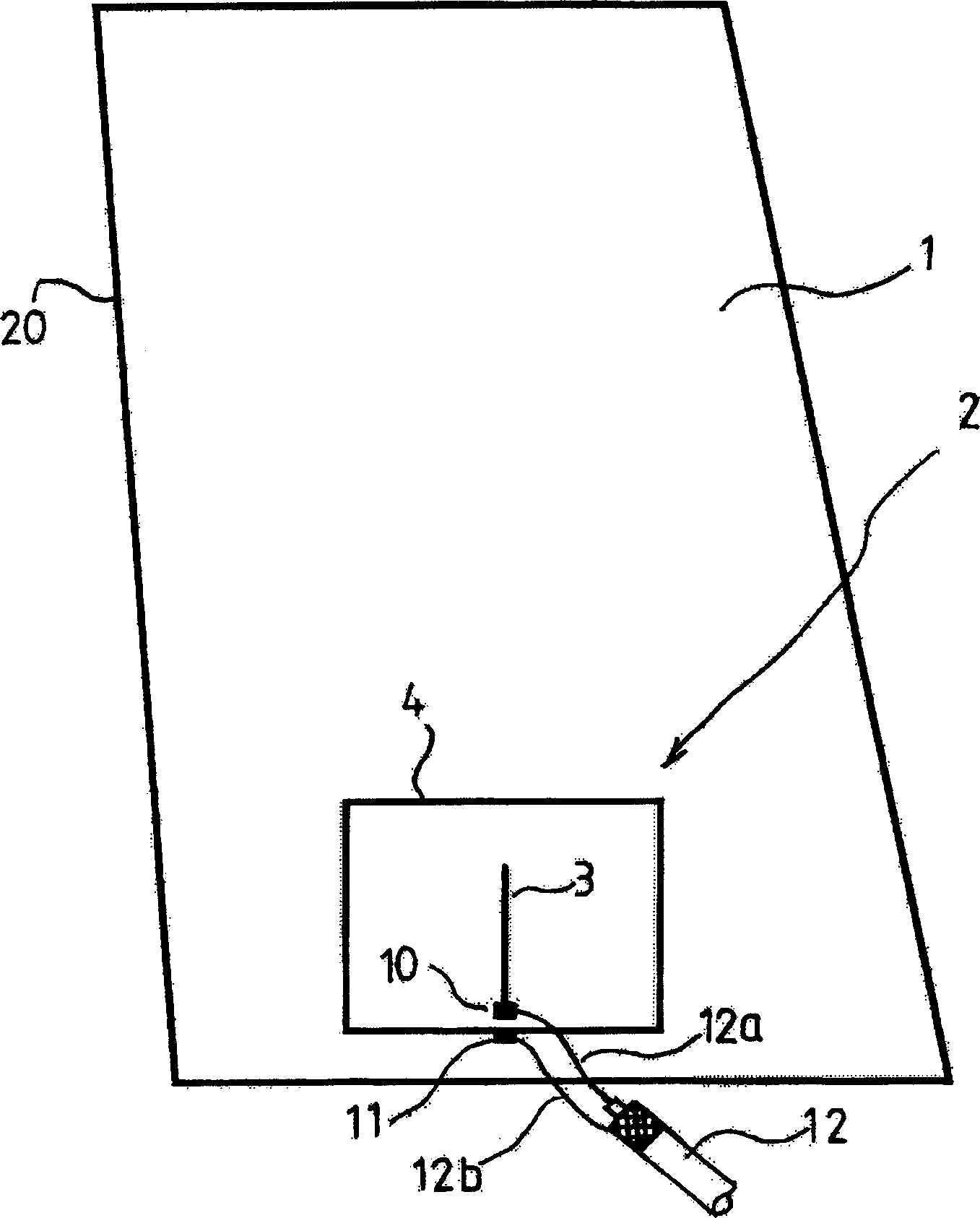
[0138] figure 1 It is a view of the antenna pattern of the present invention provided on the side window glass 1 seen from the outside of the vehicle.

[0139] figure 2 The graphics shown in are that the first element 3 and the second element 4 are printed and baked on the passenger compartment side of the glass 1, or a stamp or sheet on which the graphics are printed is firmly adhered to On the surface of an insulating member such as a resin body, and is used as an antenna for a mobile phone with a frequency of 800MHz band.

[0140] The first feeding point 10 and the second feeding point 11 are arranged in such a manner that the second feeding point 11 is located near the lower part of the first feeding point 10, and a length of one line corresponds to 1 of the wavelength of radio waves transmitted and received The vertical line of / 4 extends vertically upward from the first feeding point 10, thus making the first element 3.

[0141] The antenna 2 is printed directly on t...

example 2

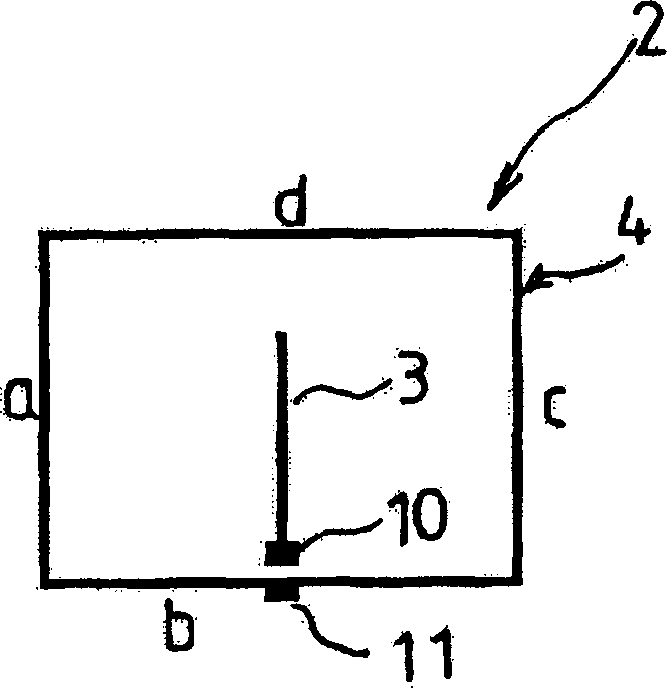
[0150] Example 2 is a modified example. The figure of Example 1 in Example 2 is modified, so that the length of the first element 3 is changed to 3 / 4 of the wavelength of the radio wave emitted and received, and the entire perimeter of the second element 4 is modified to three wavelengths, and the second element 4 is formed as image 3 The vertically elongated quadrilateral shown, the antenna pattern thus formed according to the invention is arranged on the cabin side of the glass pane.

[0151] That is, make the length of the first element 3 correspond to a line extending from the first feeding point 10 to 3 / 4 of the wavelength of the radio waves transmitted and received for the frequency of 800 MHZ, that is, the length is 165mm long, where Assuming that the wavelength shrinkage ratio of the glass plate is 0.6 at a frequency of 800 MHz, the first member 3 is vertically arranged so as to be a vertical line.

[0152] In addition, with regard to the second element 4, although t...

example 3

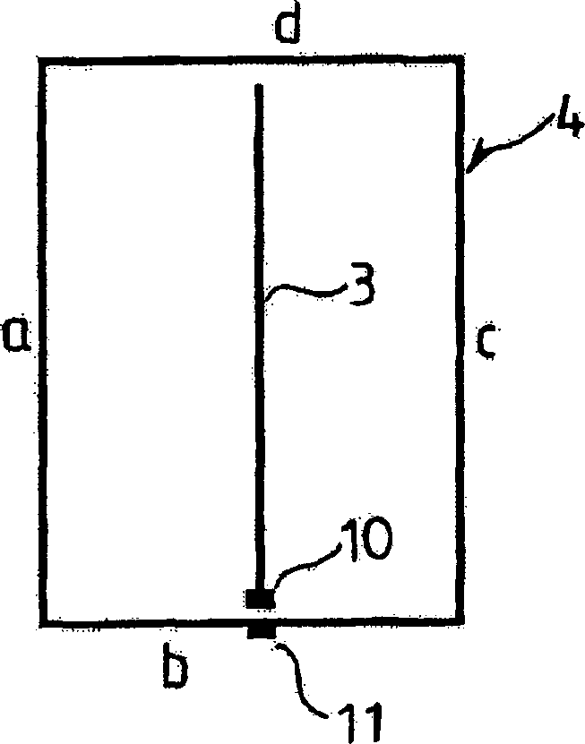
[0158] Example 3 is also a modified example. The figure of Example 1 is modified in Example 3, so that the length of the first element 3 is changed to 1 / 4 of the wavelength of the radio wave emitted and received, and the entire circumference of the second element 4 is changed to For the length corresponding to one wavelength, in addition, the shape of the second element 4 is formed as Figure 4 The deformed quadrilateral shown, the antenna pattern thus formed is used as an antenna for a mobile phone with a bandwidth of 2 GHz band. The graphics thus formed are printed and baked on the passenger cabin side of the glass plate, or a stamp or sheet on which the graphics are printed is firmly adhered to the cabin side window glass 1 or a substrate such as a resin body. on the surface of the insulating member.

[0159] The second member 4 is formed as a quadrangle having four corners up, down, left, and right and is laterally symmetrical.

[0160] Assuming that the wavelength contr...


PUM


Abstract

An antenna for vehicle, i.e. a wire antenna being arranged on the surface of the window glass of an automobile or the like, comprising a first element having a length extending from a first feeding point equal to any one of 1 / 4, 3 / 4 or 5 / 4 of the wavelength of a transmitting / receiving radio wave, and a second closed loop element having a length extending from a second feeding point, provided in the vicinity of the first feeding point, while surrounding the first element not shorter than one wavelength of the transmitting / receiving radio wave.

Description

technical field [0001] The present invention relates to a wire antenna installed on the surface of a window glass of a movable object such as a vehicle or the surface of an insulating member, which antenna is optimal for receiving FM radio broadcast waves, digital radio broadcast waves, and television broadcast waves, and for transmitting and Receives VHF or higher range radio waves such as car phones, cellular phones, personal radios, commercial radios, and PHS (Personal Handyphone System). Background technique [0002] Generally, although whip antennas are widely used as antennas for transmitting and receiving radio waves of car phones and mobile phones and for receiving TV broadcast waves, since the structure of these whip antennas requires the antenna to protrude from the car body, some defects occur. The protrusions are not the most desirable from a safety point of view and an aesthetic point of view, and the protruding antenna can cause interference and be easily damag...

Claims


Application Information

Patent Timeline
Patent Type & Authority Applications(China)
IPC IPC(8): H01Q1/22
Inventor 藤井宏征上村雅
Owner CENT GLASS CO LTD
Why Eureka
Try Eureka