
Antenna device on high-frequency RFID chip

An antenna device and chip technology, which is applied to antenna supports/installation devices, antennas, and antenna components, etc., can solve the problems of high frequency tag performance and consistency, high cost, and complicated procedures.

Inactive Publication Date: 2020-12-01
上海明矽微电子有限公司
View PDF0 Cites 0 Cited by
  • Summary
  • Abstract
  • Description
  • Claims
  • Application Information

AI Technical Summary

Problems solved by technology

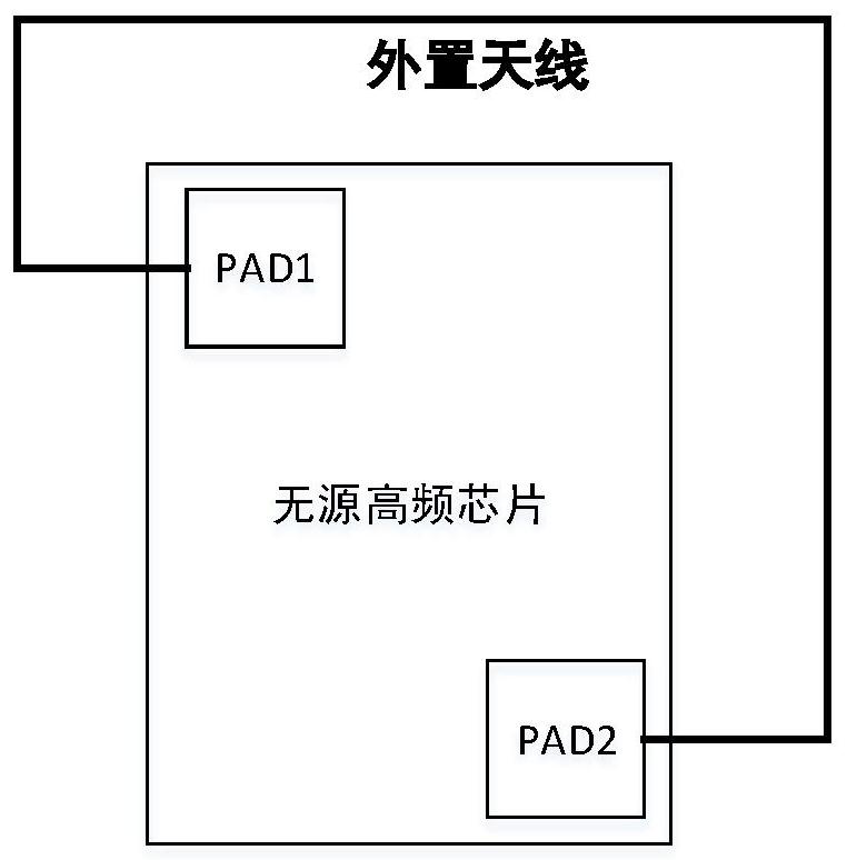
The external antenna needs to be manufactured through special technology, and the cost is high, and the antenna area is large
Welding technology also has disadvantages, such as cumbersome procedures, high cost, and the coupling capacitance generated when welding chips will have a greater impact on the performance and consistency of high-frequency tags

Method used


Image

  • Antenna device on high-frequency RFID chip
  • Antenna device on high-frequency RFID chip
  • Antenna device on high-frequency RFID chip

Examples


Embodiment Construction

[0012] based on the following figure 2 and image 3 , specifically describe the preferred embodiment.

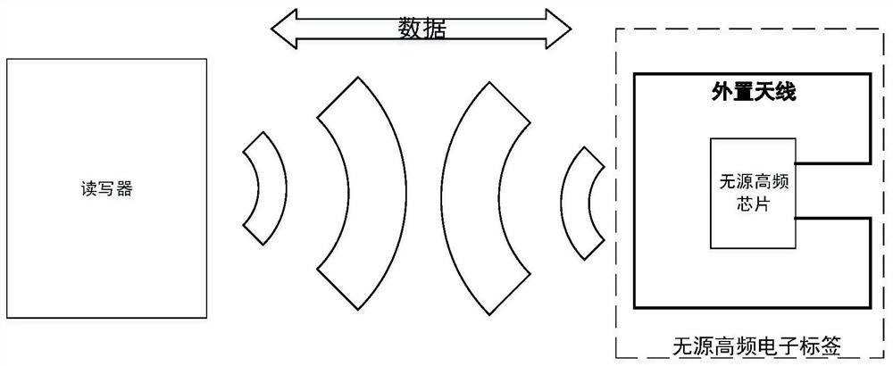
[0013] Such as figure 2 As shown, a complete high-frequency RFID system consists of readers, passive high-frequency electronic tags and data management systems.

[0014] The reader is a device that reads out the information in the tag, or writes the information that the tag needs to store into the tag. The basic composition of the reader usually includes: transceiver antenna, frequency generator, phase-locked loop, modulation circuit, microprocessor, memory, demodulation circuit and peripheral interface.

[0015] The passive high-frequency electronic tag is composed of an external antenna and a high-frequency chip (rectification circuit, demodulation circuit, modulation circuit, storage circuit and logic control circuit), which receives the microwave signal transmitted by the reader and the electromagnetic induction The coil captures energy to briefly power itself to c...


PUM


Abstract

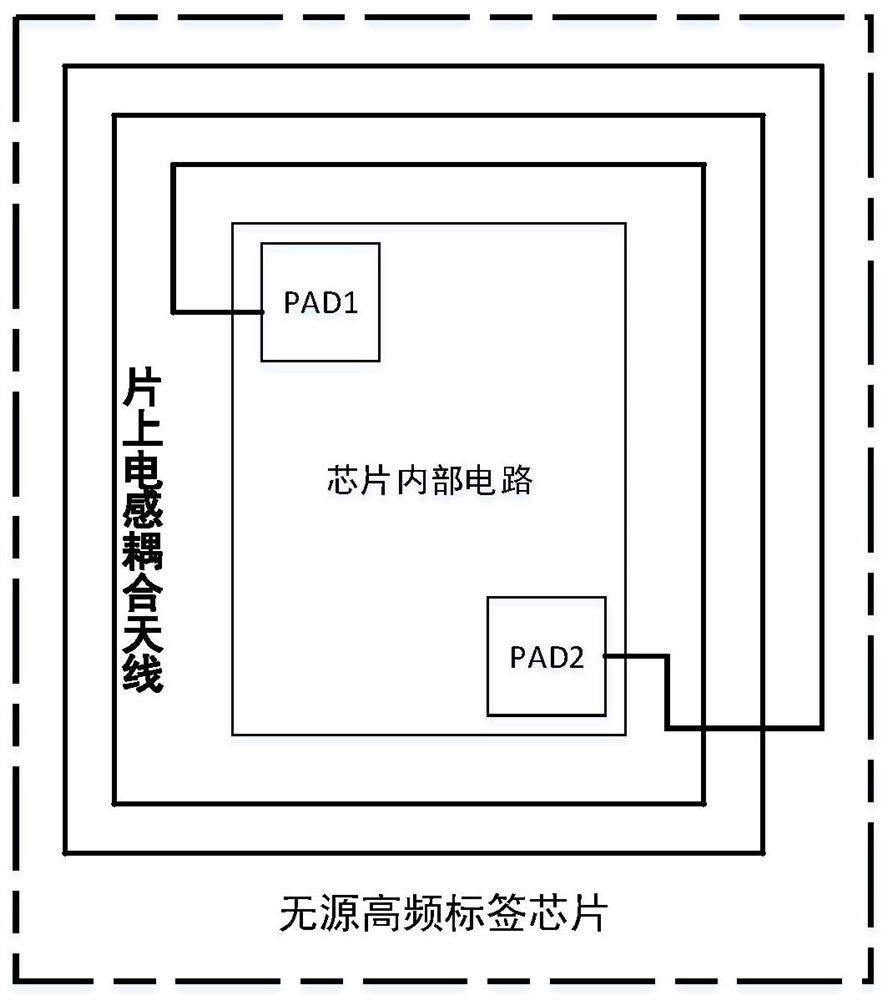
A passive high-frequency chip needs to enable an external antenna to be connected with a welding point (PAD) at the top of the chip through a welding technology. The external antenna needs to be manufactured through a special process technology, and is high in cost and large in antenna area. The welding technology also has the defects that the process is tedious, the cost is high, and the couplingcapacitance generated when the chip is welded has great influence on the performance and consistency of the high-frequency tag. The invention provides an antenna device on a high-frequency RFID chip.The invention aims to reduce the manufacturing cost of the antenna device, enable the application range of the antenna device to be wider, and manufacture a high-frequency electronic tag with highercompetitiveness.

Description

technical field [0001] The invention belongs to the technical field of integrated circuits, specifically, to the design field of high-frequency RFID chips. Background technique [0002] RFID stands for Radio Frequency Identification, which is a communication technology that can identify specific targets and read and write related data through radio signals without the need for identification systems to establish physical or optical contact with specific targets. RFID can be used as a unique ID card for each object, and it is also the basis for identification, communication and interconnection of each object in the Internet of Things. In recent years, with the development of technologies such as large-scale integrated circuits, network communications, and information security, RFID technology has entered the stage of commercial application. Due to the characteristics of high-speed moving object recognition, multi-tag simultaneous recognition and non-contact recognition, RFID...

Claims


Application Information

Patent Timeline
IPC IPC(8): H01Q1/36H01Q1/22G06K19/077
CPCG06K19/07779H01Q1/2225H01Q1/2283H01Q1/36
Inventor 韦强张建伟
Owner 上海明矽微电子有限公司
Learn More