Abnormal light source cuing method for image display apparatus and its device

An image display device and technology of light source, applied in the field of light source abnormality prompting method and device field, can solve the problems of inability to distinguish image display device, image cannot be displayed, and image display device cannot display image, etc.

Inactive Publication Date: 2006-04-26
NANJING LG TONGCHUANG COLOR DISPLAYS SYST CO LTD
View PDF0 Cites 2 Cited by
  • Summary
  • Abstract
  • Description
  • Claims
  • Application Information

AI Technical Summary

Problems solved by technology

Therefore, if the light source 126 is not working properly, the image cannot be displayed on the screen 130 of the image display device.
[0005] As mentioned above, if the light source 126 of the image display device does not work properly and the image cannot be displayed, the user cannot identify what causes the image display device to fail to display (malfunction)

Method used


Image

  • Abnormal light source cuing method for image display apparatus and its device
  • Abnormal light source cuing method for image display apparatus and its device
  • Abnormal light source cuing method for image display apparatus and its device

Examples


Embodiment Construction

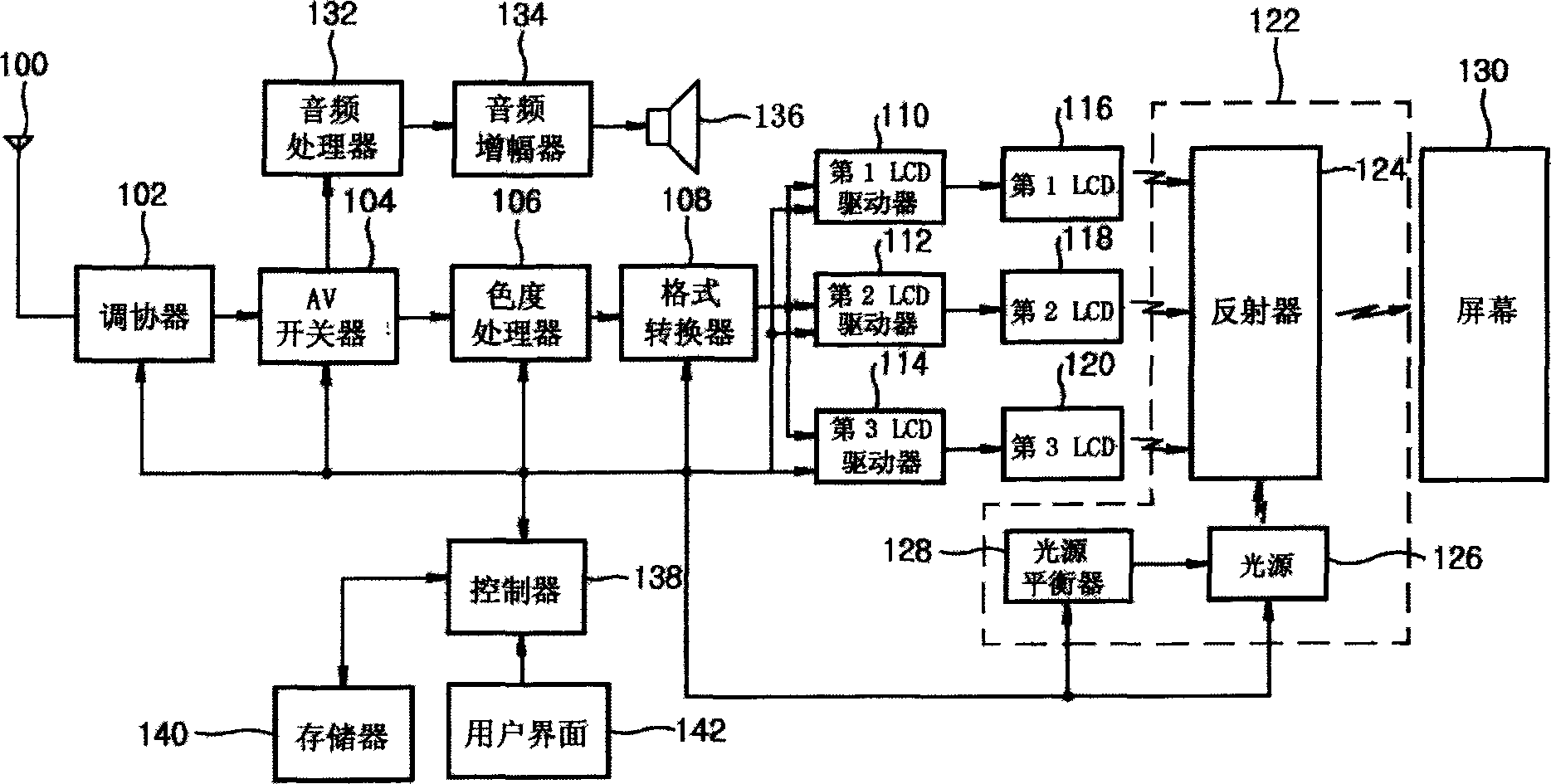
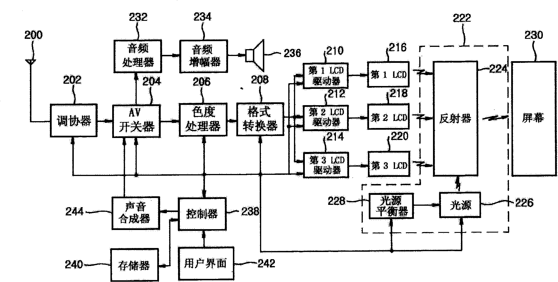
[0029] Refer to figure 2 The embodiment of the image display device of the present invention and its structure are described as follows:

[0030] The tuner 202 selects and outputs a channel from the broadcast signal received by the antenna 200 according to the control signal of the controller 238. After the AV switch 204 processes the broadcast signal adjusted and output by the tuner 202, the audio signal is sent to the audio processor 232, and the video signal is sent to the chrominance processor 206. The AV switch 204 supplies the sound signal received by the sound synthesizer 244 to the audio processor 232 according to the control command of the controller 238.

[0031] The chrominance processor 206 converts the video signal into an RGB signal and then supplies it to the format converter 208. The format converter 208 converts the output format of the current video signal into the corresponding image output format, and then provides the RGB signals to the first to third LCD dri...


PUM


Abstract

The optical source abnormal prompting method for visual display device with optical engine comprises: sensing the abnormal phenomena; outputting prompting information for sensed abnormal. Wherein, the device comprises: a luminous bulb as optical source with optical engine, a balancer for optical source to drive and control the optical source to detect abnormal and send abnormal signal, a memory to store abnormal promoting sound data, a sound mixer and tone generator to receive sound data and output composed sound, and a controller to receive and read abnormal signal from optical source to supply to said mixer.

Description

Technical field: [0001] The invention relates to an image display device, in particular to a method and a device for prompting an abnormal light source of the image display device. Background technique [0002] Refer to figure 1 A brief description of the traditional image display equipment is as follows: [0003] The tuner 102 selects and outputs a channel from the broadcast signal received by the antenna 100 according to the control signal of the controller 138. The AV switch 104 processes the broadcast signal adjusted and output by the above-mentioned tuner 102, sends the audio signal to the audio processor 132, and sends the video signal to the chrominance processor 106. The chrominance processor 106 converts the video signal into an RGB signal and supplies it to the format converter 108. The format converter 108 converts the output format of the current video signal into the corresponding image output format, and then provides the RGB signals to the first to third LCD drive...

Claims


Application Information

Patent Timeline
Patent Type & Authority Applications(China)
IPC IPC(8): H05B37/03G08B5/00G08B21/00G09G3/36
Inventor 刘原旭
Owner NANJING LG TONGCHUANG COLOR DISPLAYS SYST CO LTD
Why Eureka
Try Eureka