Method of analyzing electrolytic copper plating solution, and analyzing device therefor and production method for semi-conductor product
An analysis method, copper electroplating technology, applied in the direction of material analysis, analysis materials, measuring devices, etc. by electromagnetic means, can solve the problem of filling deterioration and other problems
- Summary
- Abstract
- Description
- Claims
- Application Information
AI Technical Summary
Problems solved by technology
Method used
Image
Examples
Embodiment 1
[0089] Hereinafter, the invention described in claims 1-6 will be described in detail through Examples 1-3. device for use Figure 6 device of the structure.
[0090] From the copper plating tank for filling through holes in work, take out 100ml of the plating solution (determined plating solution 5) measured by CVS to control the concentration of additives, put it into a beaker, and place it on the special frame 6. However, since the state of the measured plating solution would change if it was left standing, the plating solution was taken out as a liquid within 2 days.
[0091] In reference electrode 2, a dual structure Ag / AgCl reference electrode (external liquid is 10vol% H 2 SO 4 , the internal liquid is 0.1mol / L KCl 10vol%H 2 SO 4 , Ag / AgCl in the internal liquid), in the working electrode 3, a platinum rotating electrode (with an electrode area of 4πmm 2 ), the opposite pole 4 uses a copper column (diameter 8mm).
[0092] The current density of the platinum rot...
Embodiment 2
[0095] The plating bath was taken out from the copper plating tank for filling via holes in operation every two months, and the constant current potential was measured under the same measurement conditions as in Example 1. The above liquids are all measured according to CVS, and the concentration of additives is controlled within a certain concentration.
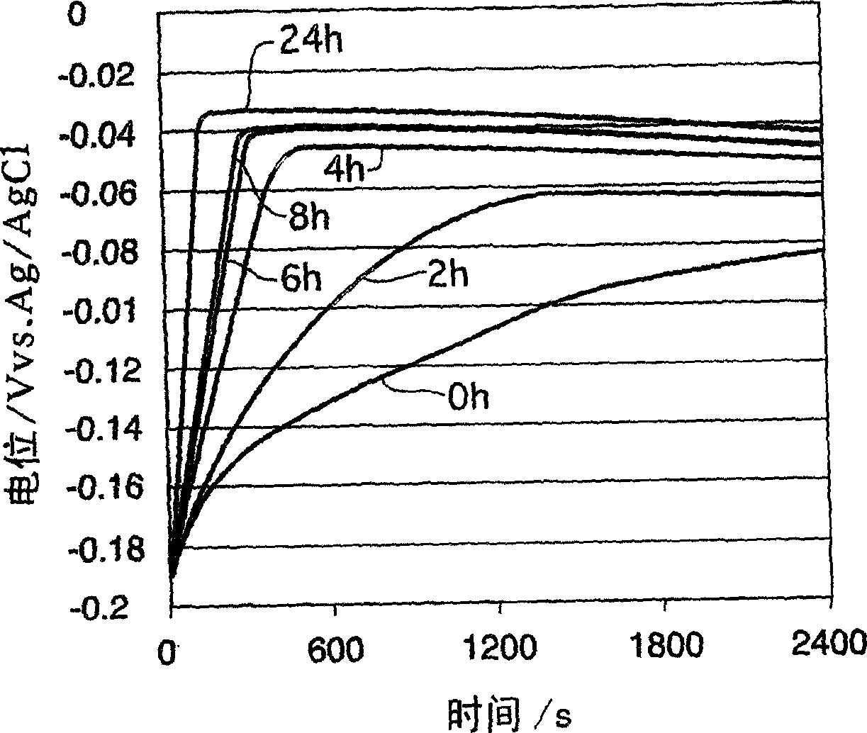
[0096] exist Figure 13 In , the constant current potential measurement results of a new liquid having the same additive concentration as the above-mentioned liquid and a plating solution every two months are shown. exist Figure 14 in, means Figure 13 dx of constant current potentiometry results shown. From Figure 13 , 14 It can be seen that even if the additive concentration is controlled within a certain concentration by CVS measurement, the fillability will decrease.
Embodiment 3
[0098] Prepare a new liquid and divide it into 2 parts, one part does not put any substance, and the other part puts the area limited to 100cm 2 / L phosphorus-containing copper plate, placed in a static state for 48 hours. Plating was carried out in via holes with a diameter of 100 μm and a depth of 75 μm using two liquids, the former filled via holes and the latter unfilled via holes.
[0099] The two liquids are measured by CVS to determine the concentrations of accelerators and inhibitors, and the concentrations are only different in the degree of error. It can be seen that the fillability of via holes cannot be judged only by controlling the concentration of additives through CVS measurement.
PUM
| Property | Measurement | Unit |
|---|---|---|
| hardness | aaaaa | aaaaa |
| hardness | aaaaa | aaaaa |
| ductility | aaaaa | aaaaa |
Abstract
Description
Claims
Application Information
 - R&D
- Intellectual Property
- Life Sciences
- Materials
- Tech Scout
- Unparalleled Data Quality
- Higher Quality Content
- 60% Fewer Hallucinations
Browse by: Latest US Patents, China's latest patents, Technical Efficacy Thesaurus, Application Domain, Technology Topic, Popular Technical Reports.
© 2025 PatSnap. All rights reserved.Legal|Privacy policy|Modern Slavery Act Transparency Statement|Sitemap|About US| Contact US: help@patsnap.com


