Light guide panel and surface emitting device

A light guide plate and reflective surface technology, applied in optics, nonlinear optics, diffuser elements, etc., can solve the problems of difficult manufacturing of light guide plates and small control range of the angle of outgoing light, etc., and achieve the effect of cost saving and simple structure

Inactive Publication Date: 2006-05-03
TSINGHUA UNIV +1
View PDF2 Cites 19 Cited by
  • Summary
  • Abstract
  • Description
  • Claims
  • Application Information

AI Technical Summary

Problems solved by technology

[0009] In order to solve the shortcomings of the light guide plate in the prior art, which are difficult to manufacture and form and the control range of the angle of the emitted light is small, the present invention provides a light guide plate that is easy to form and can flexibly control the angle of the emitted light

Method used


Image

  • Light guide panel and surface emitting device
  • Light guide panel and surface emitting device
  • Light guide panel and surface emitting device

Examples


Embodiment Construction

[0030] The present invention will be described in further detail below in conjunction with the accompanying drawings.

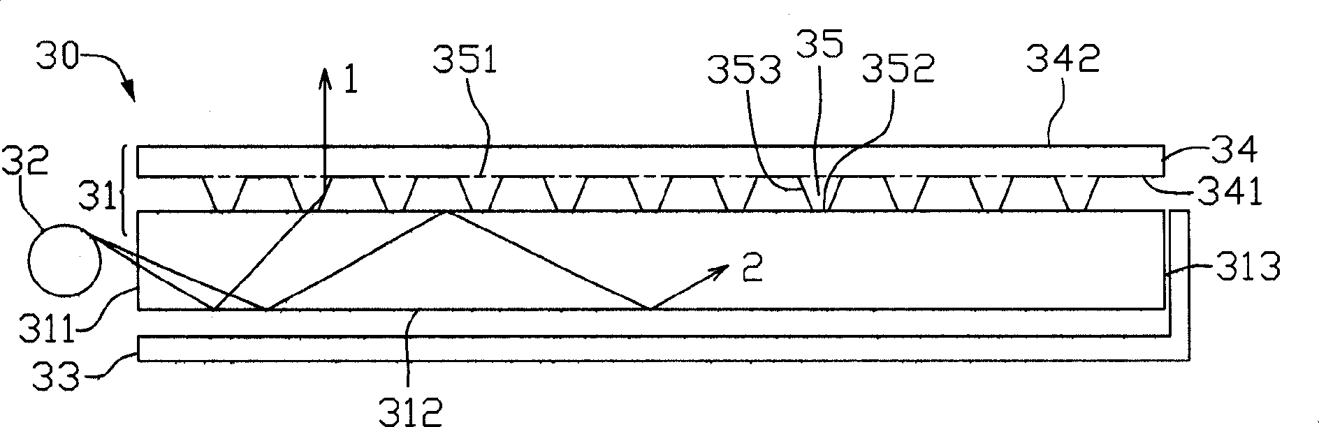
[0031] see image 3 , is a schematic structural view of the surface light-emitting device provided by the present invention. The surface emitting device 30 includes a light guide plate 31 , at least one light source 32 close to the side of the light guide plate 31 , and a reflection sheet 33 close to the bottom of the light guide plate 31 . Wherein, the light guide plate 31 has an upper and lower structure, and the lower structure has at least one light incident surface 311 close to the light source 32 , a bottom reflective surface 312 , and an end surface 313 opposite to the light incident surface 312 . The upper structure includes a substrate 34 . The substrate 34 at least has a substrate bottom surface 341 facing the lower layer of the light guide plate and a light emitting surface 342 opposite to the substrate bottom surface 341 . Protrusions 35 are arr...


PUM

PropertyMeasurementUnit
lengthaaaaaaaaaa
widthaaaaaaaaaa

Abstract

The invention provides a light driving plate and panel illuminating apparatus. The light driving plate has up and down two layer structure, the down layer comprises at least one light incidence panel used to receive the light from the light source and a back-light panel on the bottom panel; the up layer comprises a base plate with a light exit panel on the surface of the upper panel and the bump arrange-formed on the bottom panel near the down layer of the light driving plate on the base plate. The panel illuminating apparatus adopts the light driving plate to evenly eject the light from the light exit panel of the light driving plate. It arranges the ladder structure on the up layer bottom panel of the light driving plate which can control the light exit angle of the light exit panel.

Description

【Technical field】 [0001] The present invention relates to a surface light-emitting device, in particular to a light guide plate with protrusions and a surface light-emitting device thereof. 【Background technique】 [0002] In recent years, flat panel displays have developed rapidly and have been widely used in fields such as personal computers, televisions, mobile communications, and consumer electronics, becoming a major platform for information technology. At the same time, the requirements of electronic products for flat-panel display devices (such as liquid crystal display devices) continue to increase, and high brightness, light and thin, low cost, low energy consumption, and long life have become the development direction of surface light-emitting devices. [0003] According to the position of the light source, surface light-emitting devices can be divided into two types: direct-light type and side-mounted type. The direct type refers to placing the light source direct...

Claims


Application Information

Patent Timeline
Patent Type & Authority Applications(China)
IPC IPC(8): G02F1/1335G02B5/02
Inventor 杨兴朋金国藩严瑛白冯迪刘海涛谭峭峰
Owner TSINGHUA UNIV
Why Eureka
Try Eureka