Backlight module assembly
A technology of backlight module and light guide plate, which is applied in optics, nonlinear optics, instruments, etc., can solve the problems of lamp tube design backlight module, etc., and achieve the effects of reducing light energy loss, good scattering effect, and improving uniformity
- Summary
- Abstract
- Description
- Claims
- Application Information
AI Technical Summary
Problems solved by technology
Method used
Image

Examples
Embodiment Construction
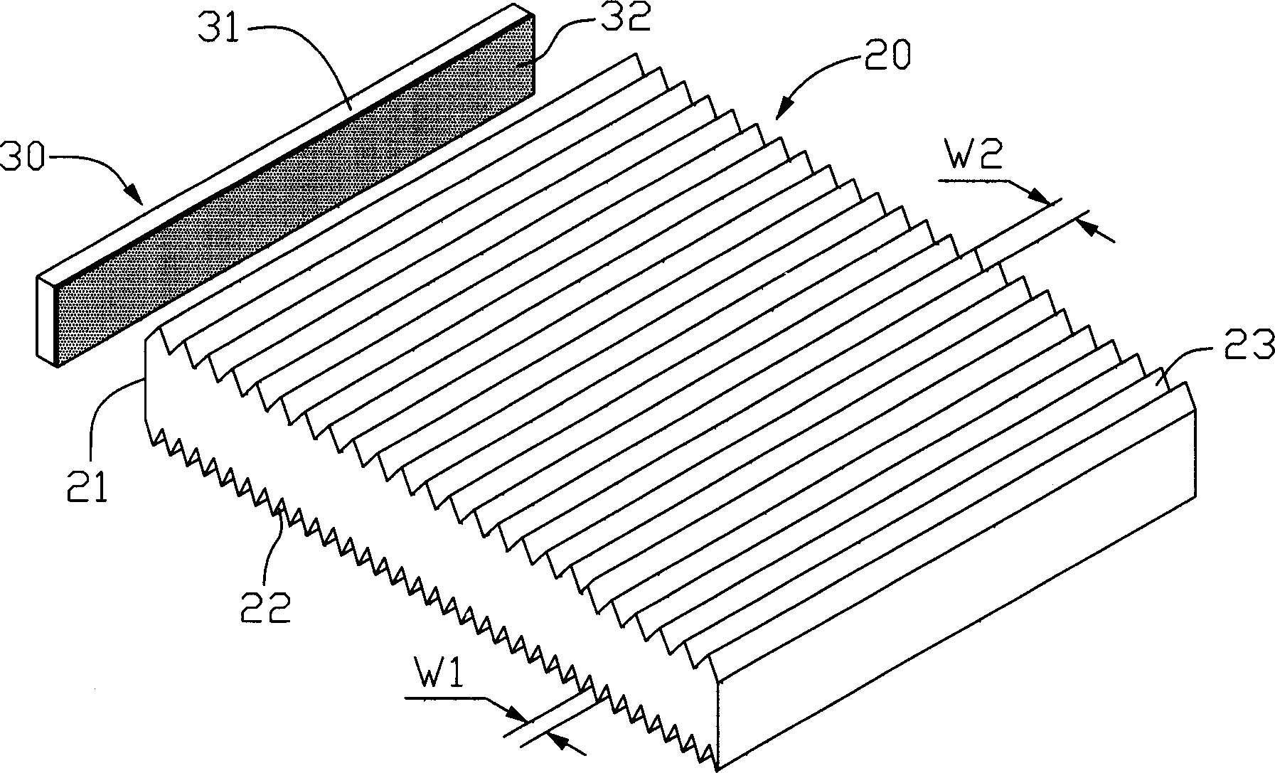
[0018] The following illustrates the backlight module provided by the present invention in combination with icons:
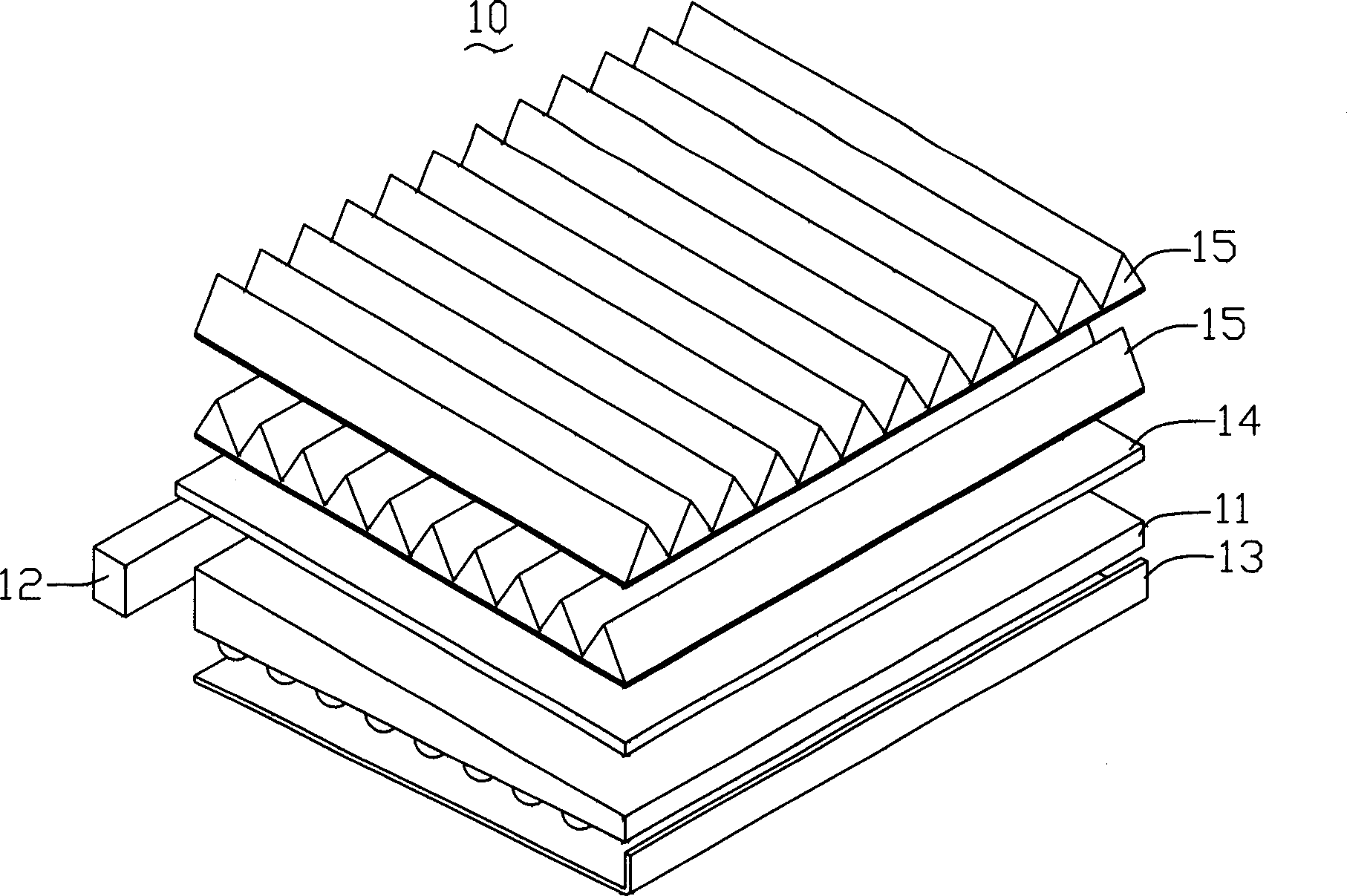
[0019] see figure 2 The backlight module provided by the present invention includes a flat cold cathode lamp 30 and a light guide plate 20. The light guide plate 20 can be flat or wedge-shaped, and its shape is not limited. It includes a light incident surface 21, A light-emitting surface 23 and a reflecting surface 22 opposite to the light-emitting surface, V-shaped grooves are formed on the reflecting surface 22 and the light-emitting surface 23; the cold cathode lamp 30 is located on the light-incident surface 21 side of the light guide plate 20, wherein the A nano-scale silicon dioxide particle layer 32 is formed on the surface of the lamp tube 31 of the cold cathode lamp 30 .
[0020] Wherein the cold cathode lamp 30 is designed to be flat so that it is close to a side light source, which is beneficial to improve the uniformity of the backlight source.
...
PUM
| Property | Measurement | Unit |
|---|---|---|
| Diameter | aaaaa | aaaaa |
| Thickness | aaaaa | aaaaa |
Abstract
Description
Claims
Application Information
PatSnap Eureka turns technology decisions into work you can execute. Powered by our Innovation Knowledge Graph, it runs expert workflows across engineering, life sciences, materials and intellectual property. Get your review-ready output in minutes.


