Smectic state liquid crystal dyeing color display device

A display and smectic technology, which is applied to instruments, nonlinear optics, optics, etc., can solve the problems of complex peripheral drive circuits of display devices, unsatisfactory display effects, and the impact of lightness of display devices, etc., to improve the display effect. , the effect of eliminating parallax defects, production process complexity and production cost reduction

Inactive Publication Date: 2012-05-23
HALATION PHOTONICS CORP
View PDF4 Cites 3 Cited by
  • Summary
  • Abstract
  • Description
  • Claims
  • Application Information

AI Technical Summary

Problems solved by technology

In practical applications, the reflectivity of the light will not exceed 30% after passing through the six substrate layers, which makes the reflectivity of the display device very low and cannot meet the display requirements.
In addition, even when the smectic liquid crystal in each layer structure is in a fully transparent state, the dichroic dye molecules still have a certain light absorption and present a certain color, which will further reduce the light transmittance, generally It will be much lower than 30%, and the display effect is not satisfactory
At the same time, the entire image of the display device is equivalent to being displayed on three-layer planes, and the reflection of light on different planes will produce parallax, which affects the display effect, and the liquid crystal molecules in the three-layer structure must be driven every time it is displayed. Therefore, the peripheral driving circuit of the display device is quite complicated, and the lightness of the entire display device is affected.
[0005] In summary, there is always a contradiction between the display effect and energy consumption of traditional liquid crystal displays
Although the existing smectic liquid crystal display devices capable of displaying images in color have achieved the purpose of energy saving, the energy saving is at the expense of poor display effect.

Method used


Image

  • Smectic state liquid crystal dyeing color display device
  • Smectic state liquid crystal dyeing color display device
  • Smectic state liquid crystal dyeing color display device

Examples


Embodiment Construction

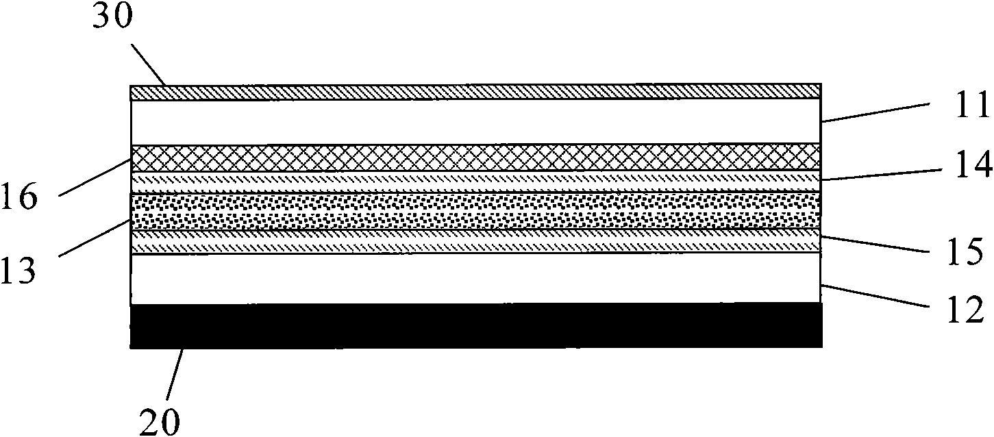
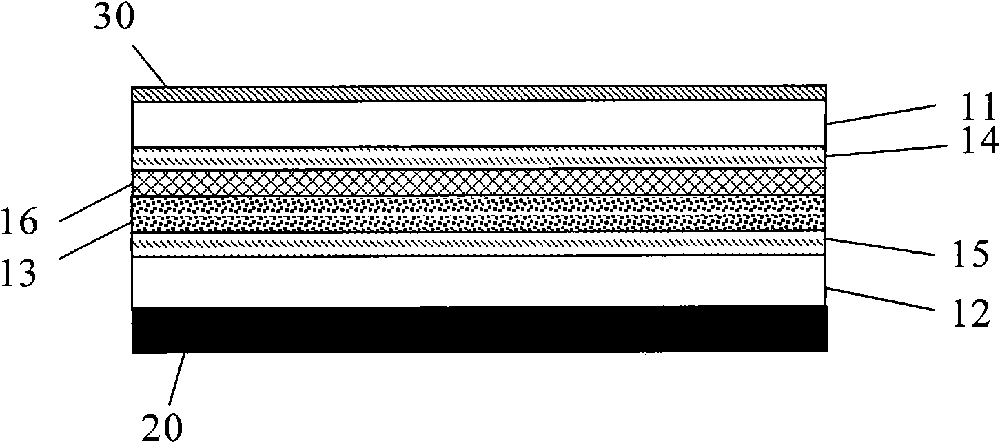
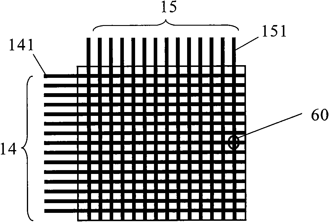
[0019] Such as Figure 1 to Figure 2 As shown, the smectic liquid crystal dyeing color display of the present invention includes a first base layer 11 and a second base layer 12, and the materials of the first base layer 11 and the second base layer 12 can be glass or plastic. Wherein, plastics can be transparent plastic film, also can be transparent hard plastic plate, be provided with mixed layer 13 between this first matrix layer 11 and this second matrix layer 12, this mixed layer 13 is made of smectic liquid crystal, additive , dichroic dyes, the first base layer 11 is provided with a first conductive electrode layer 14 on the side facing the mixed layer 13, and the second base layer 12 is provided with a second conductive electrode layer 12 facing the mixed layer 13. The conductive electrode layer 15, the first conductive electrode layer 14 and the second conductive electrode layer 15 are connected to an external drive control device (not shown in the figure), the first ...


PUM


Abstract

The invention discloses a smectic state liquid crystal dyeing color display device which comprises a first substrate layer and a second substrate layer, wherein a mixing layer is arranged between the first substrate layer and the second substrate layer; the mixing layer is formed by mixing smectic state liquid crystal, additive and dichroic dye; a first conductive electrode layer is arranged at one side of the first substrate layer towards the mixing layer; a second conductive electrode layer is arranged at one side of the second substrate layer towards the mixing layer; a color film layer is arranged at one side of the first conductive electrode layer or one side of the second conductive electrode layer; the dichroic dye is black; and a backlight source is arranged at one side of the second substrate layer towards outside. The smectic state liquid crystal dyeing color display device adopts the image-forming principles of ways of scattering and transmission so as to realize the effect of all-color image display.

Description

technical field [0001] The invention relates to a display device, in particular to a smectic liquid crystal dyeing color display capable of displaying images in full colors. Background technique [0002] Liquid crystal display is currently one of the most widely used and most promising flat panel display devices. [0003] Traditional liquid crystal displays are all backlight structure displays, which include multiple optical film layers such as polarizers, prism sheets, and color filters stacked in sequence. The polarizers and color filters are indispensable for realizing color display of images. An important part of. In practical applications, about 50% of the light energy will be lost when the light passes through the polarizer, and more than 40% of the light energy will be lost when it passes through the RGB color filter, which makes the light transmission rate of the display itself very low. Therefore, in order to achieve suitable brightness and contrast for the displa...

Claims


Application Information

Patent Timeline
Patent Type & Authority Applications(China)
IPC IPC(8): G02F1/1335G02F1/1333G02F1/1343G02F1/13357
Inventor 孙刚万丽芳田丽
Owner HALATION PHOTONICS CORP
Why Eureka
Try Eureka