Optical fiber gyroscope employing single-polarized-output polarization-maintaining loop device

A fiber optic gyroscope and polarization-maintaining fiber technology, applied in the field of gyroscopes, can solve problems such as loss of light energy

Active Publication Date: 2015-04-29
ZHEJIANG UNIV
View PDF3 Cites 4 Cited by
  • Summary
  • Abstract
  • Description
  • Claims
  • Application Information

AI Technical Summary

Problems solved by technology

The disadvantage of this gyroscope is that when the light beam goes back and forth to the polarization maintainin

Method used


Image

  • Optical fiber gyroscope employing single-polarized-output polarization-maintaining loop device
  • Optical fiber gyroscope employing single-polarized-output polarization-maintaining loop device

Examples


Embodiment example

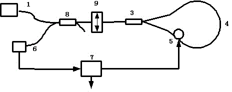
[0011] Implementation case: Broad-spectrum light source 1 uses 1310 nanometer high-polarization semiconductor super-radiation diodes. The single-polarization output polarization-maintaining circulator is characterized by only transmitting one polarization mode and blocking the other polarization mode. The extinction ratio is 30dB. Sensing The environmentally friendly polarization beam splitter uses a 1:1 splitting ratio. The polarization-maintaining fiber optic sensing ring uses 500 meters of fiber with an outer diameter of 98 mm. The phase modulator uses a few meters of fiber to be wound on a piezoelectric ceramic ring with an intrinsic frequency of 29.5 kHz. The photodetector uses PIN-FET components, and the signal processing unit uses a lock-in amplifier. The optical power incident on the photodetector is 10 microwatts, and the long-term zero drift of the experimental gyro is 0.2° / hour.

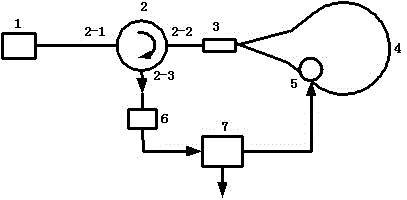
[0012] For comparison, the traditional gyroscope that uses the same light source, the sam...


PUM


Abstract

The invention discloses an optical fiber gyroscope employing a single-polarized-output polarization-maintaining loop device. Light emitted by a broadband light source enters an end 2-1 of the polarization-maintaining loop device of the light source, a polarized mode is output from an end 2-2 of the polarization-maintaining loop device, the light is split into an upper light beam and a lower light beam through a polarization-maintaining beam splitter of a sensing ring, and the upper light beam clockwise returns to the polarization-maintaining beam splitter through the polarization-maintaining optical fiber sensing ring and a phase modulator; the lower light beam anticlockwise returns to the polarization-maintaining beam splitter through the phase modulator and the polarization-maintaining optical fiber sensing ring; the upper light beam and the lower light beam are synthesized by the polarization-maintaining beam splitter to form interference, the interfered light beam is input through the end 2-2 of the polarization-maintaining loop device and output from an end 2-3 of the polarization-maintaining loop device, a photoelectric detector converts a light signal into an electric signal by and input the electric signal into a signal processing unit, and the signal processing unit generates a signal added to the phase modulator and simultaneously outputs a rotary signal of the gyroscope relative to an inertial reference system. The optical fiber gyroscope can reduce light energy loss caused by the polarization-maintaining loop device of the light source and the use of elements.

Description

Technical field [0001] The present invention relates to a gyroscope, in particular to an optical fiber gyroscope using a single polarization output polarization maintaining circulator. Background technique [0002] Traditional fiber optic gyros such as figure 1 Shown. The light emitted by the broad-spectrum light source 1 is divided into two by the light source polarization-maintaining beam splitter 8. One beam is input to the polarization-maintaining polarizer 9, and then divided into two by the sensor environmental protection polarization beam splitter 3. Clockwise through the polarization-maintaining fiber sensor ring 4, phase modulator 5, and return to the polarization-maintaining beam splitter 3; the lower beam passes through the phase modulator 5, the polarization-maintaining fiber sensor ring 4 in a counterclockwise direction and then returns to the polarization-maintaining beam splitter 器3; The two clockwise light and counterclockwise light are combined by the polarizatio...

Claims


Application Information

Patent Timeline
IPC IPC(8): G01C19/72
CPCG01C19/721
Inventor 周柯江张敏杰周芝福李晓炜胥晓春张瑜
Owner ZHEJIANG UNIV
Why Eureka
Try Eureka