Electromagnetic relay

An electromagnetic relay and current technology, applied in the direction of electromagnetic relay, relay, electromagnetic relay detailed information, etc., can solve the problem that the internal resistance of the contact circuit side cannot be reduced, and achieve the effect of ensuring contact stability

Inactive Publication Date: 2006-05-10
DAIICHI ELECTRIC +1
View PDF3 Cites 5 Cited by
  • Summary
  • Abstract
  • Description
  • Claims
  • Application Information

AI Technical Summary

Problems solved by technology

[0005] In the related prior art example, since the movable contact piece 8 needs to be made of a spring plate, the internal resistance on the contact circuit side cannot be reduced.
Considering the reduction of the resistance, the plate of the movable piece on which the contact is installed should be thick, and in the structure held by the leaf spring, since the movable contact 9 with a large weight is fixed at the front end, there is a possibility that the contact may be caused by impact. misuse

Method used


Image

  • Electromagnetic relay
  • Electromagnetic relay
  • Electromagnetic relay

Examples


Embodiment Construction

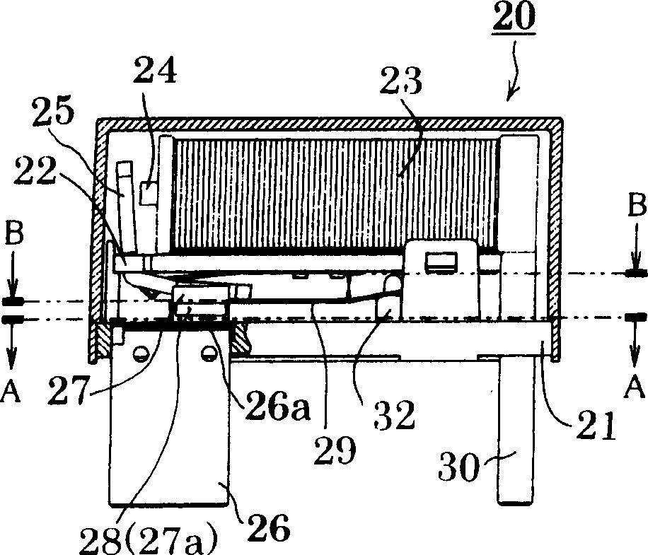
[0032] The present invention can make the internal resistance on the contact circuit side as small as possible and the purpose of conducting a large current can be achieved by providing an electromagnetic relay with an electromagnetic drive block formed by a coil, an iron core, a yoke and an armature, And each end of a pair of terminals fixed on the substrate is provided with a fixed contact, and a moving spring of a movable contact is provided at a position corresponding to each fixed contact. , the armature drives the moving spring and opens and closes the contact circuit, wherein the moving spring is held on the base body in a way of holding both ends, and is arranged side by side with the above-mentioned terminal piece, and a movable contact is provided on the moving spring.

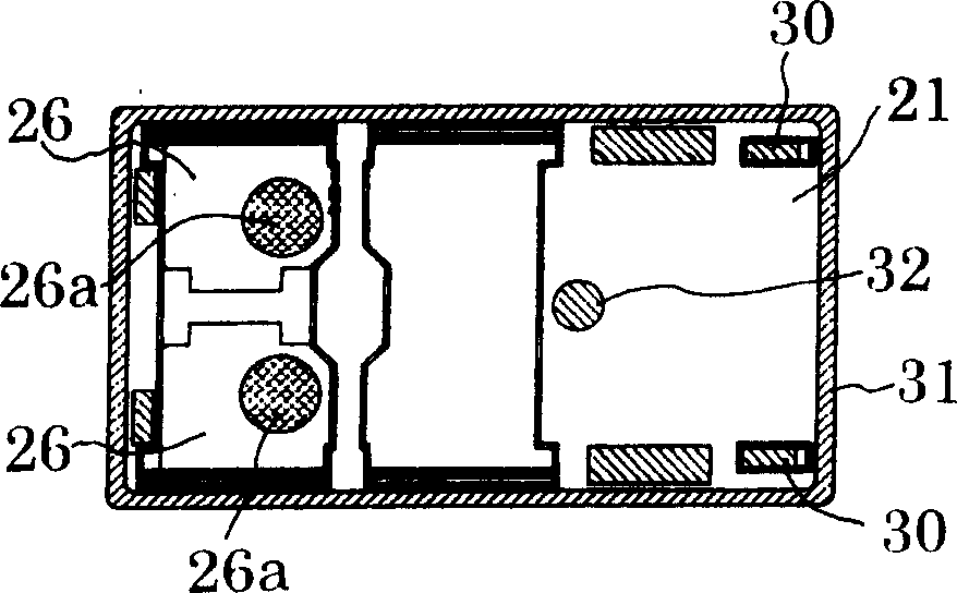
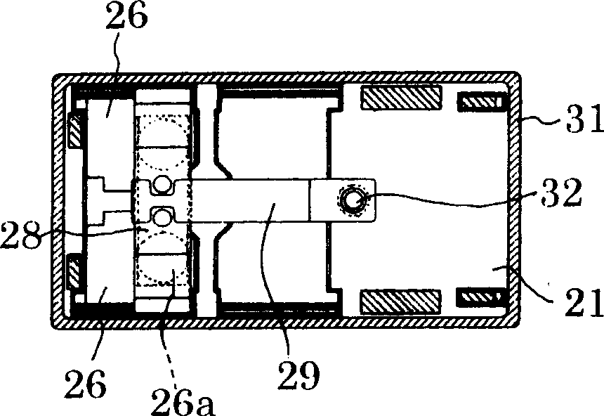
[0033] Figure 1 (movable plate and movable contact described later) and Figure 4a with Figure 4b In (no movable plate), 20 denotes an electromagnetic relay of the present invention. This electrom...


PUM


Abstract

The invention provides a small electromagnetic relay which makes the internal resistance of the contact circuit as small as possible and can conduct a large current. An electromagnetic drive block, and a fixed contact (26a) is provided on each end of a pair of terminals (26) fixed on the substrate (21), and a movable contact (26a) is provided at a position corresponding to each fixed contact (26a). The moving spring (27) of the contact point (27a), according to the presence or absence of current to the coil (23), the armature (25) drives the moving spring (27) and opens and closes the contact circuit, wherein the moving spring (27) It is held on the base body (21) in a manner of holding at both ends, and arranged in parallel with the above-mentioned terminal piece, and the above-mentioned movable contact (27a) is provided on the moving spring (27).

Description

technical field [0001] The invention relates to an electromagnetic relay, in particular to an improved small electromagnetic relay which makes the internal resistance of the contact circuit as small as possible and can conduct large current. Background technique [0002] Existing this small electromagnetic relay 1 is in Figure 11 described in . Figure 11 In order to show a schematic longitudinal side view of the electromagnetic relay 1, the electromagnetic relay 1 in this figure is formed by the following parts, which has: a yoke 3 which is vertically provided on an insulating base 2 formed by molding; The iron core 4 fixed on the top; the iron core 4 is arranged at the center and wound on the coil 5 on the bobbin (not shown in the figure); the upper end of the above-mentioned yoke 3 can be freely rotated as a pivot The armature 6; the insulating plate 7 which is arranged in front of the lower end of the armature 6 and reciprocates in the front and rear direction with the ...

Claims


Application Information

Patent Timeline
IPC IPC(8): H01H50/54
CPCH01H1/20H01H50/14H01H50/30H01H50/54H01H50/56
Inventor 武田秀昭望月直哉
Owner DAIICHI ELECTRIC
Why Eureka
Try Eureka