
High-speed dynamic vehicle overload detecting method based on bridge strain

A detection method and vehicle technology, applied to measuring devices, instruments, weighing, etc., can solve the problems of low precision and large errors

Inactive Publication Date: 2006-05-17
SHANGHAI JIAO TONG UNIV
View PDF0 Cites 20 Cited by
  • Summary
  • Abstract
  • Description
  • Claims
  • Application Information

AI Technical Summary

Problems solved by technology

[0004] The purpose of the present invention is to overcome the deficiencies of the prior art and provide a bridge strain-based high-speed dynamic vehicle overload detection method to improve the efficiency of static load measurement, 24-hour non-stop monitoring, and solve the strain gauge measurement of bridge vibration weighing The accuracy of the result is low and the error is large, and the practical effect of engineering is achieved.

Method used


Image

  • High-speed dynamic vehicle overload detecting method based on bridge strain
  • High-speed dynamic vehicle overload detecting method based on bridge strain
  • High-speed dynamic vehicle overload detecting method based on bridge strain

Examples


Embodiment Construction

[0035] 1. Calculate bridge strain

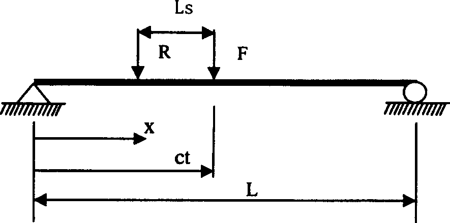
[0036] The simply supported beam model is adopted for the bridge, and when the vehicle passes the bridge deck, it is simplified to the distance L s The two point forces pass through the bridge deck at a constant speed of speed c, F represents the front axle, and R represents the rear axle. Such as figure 1 Shown:

[0037] The equation of motion for a vehicle passing the bridge is:

[0038] ρ ∂ 2 υ ( x , t ) ∂ t 2 + C ∂ υ ( x , t ) ∂ t + ...


PUM


Abstract

The present invention relates to a high-speed dynamic vehicle overload detection method based on bridge strain, belonging to the field of detection technology. Said invention uses strain sensor as field sensing device to measure bridge surface strain due to running vehicle, and utilizes integral operation to eliminate the influence of vehicle vibration on the calculated result so as to further obtain load weight value, then utilizes aid load weight value to compare it with standard load weight value pre-stored in data base so as to judge overload of said vehicle.

Description

technical field [0001] The invention relates to a detection method in the technical field of measurement, in particular to a high-speed dynamic vehicle overload detection method based on bridge strain. Background technique [0002] In the process of transporting goods, road vehicles are generally overloaded. Overloaded vehicles will cause serious damage to the roads, resulting in very serious direct economic losses, while overloading also leads to a large number of traffic accidents. Before the advent of Weigh-in-Motion (WIM), all vehicle weighings were carried out while static. The weighing of the vehicle during the static measurement is exactly equal to the gravitational force of the static vehicle, and this weighing method is the most accurate method. However, this traditional weighing method has its own shortcomings. On the one hand, it needs to set up a special site or weighing station at the roadside or intersection, the measurement efficiency is low, and it cannot b...

Claims


Application Information

Patent Timeline
Patent Type & Authority Applications(China)
IPC IPC(8): G01G19/03
Inventor 李建勋郑军庭
Owner SHANGHAI JIAO TONG UNIV
Learn More