Method for making bent-tube and its special equipment

A production method and technology of special equipment, which are applied to the production of elbows and the field of special equipment, can solve the problems such as the inability to take out the inner core of the elbows, and achieve the effects of low power, low energy consumption, and guaranteeing the quality of the elbows.

Inactive Publication Date: 2006-05-24
车英年
View PDF0 Cites 6 Cited by
  • Summary
  • Abstract
  • Description
  • Claims
  • Application Information

AI Technical Summary

Problems solved by technology

The disadvantage is that only elbows can be made, and the inner core of the bent pipe cannot be taken out

Method used


Image

  • Method for making bent-tube and its special equipment
  • Method for making bent-tube and its special equipment
  • Method for making bent-tube and its special equipment

Examples


Embodiment Construction

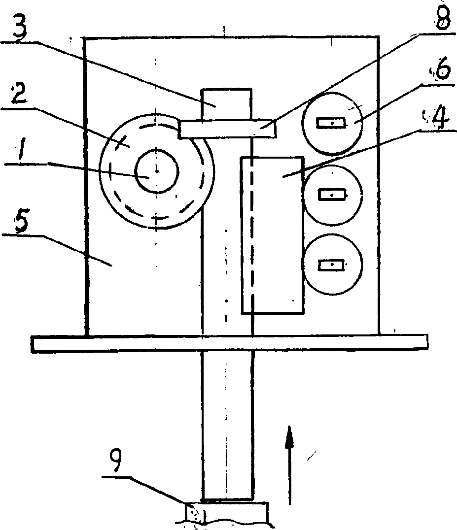
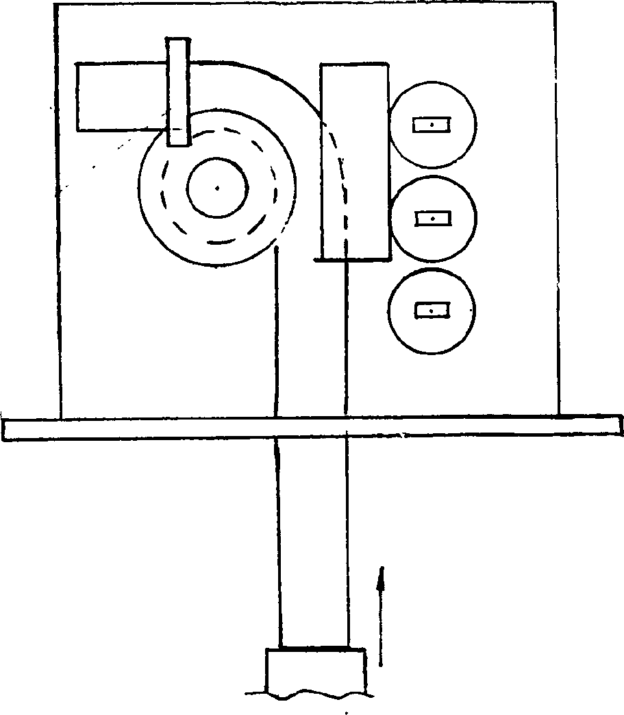
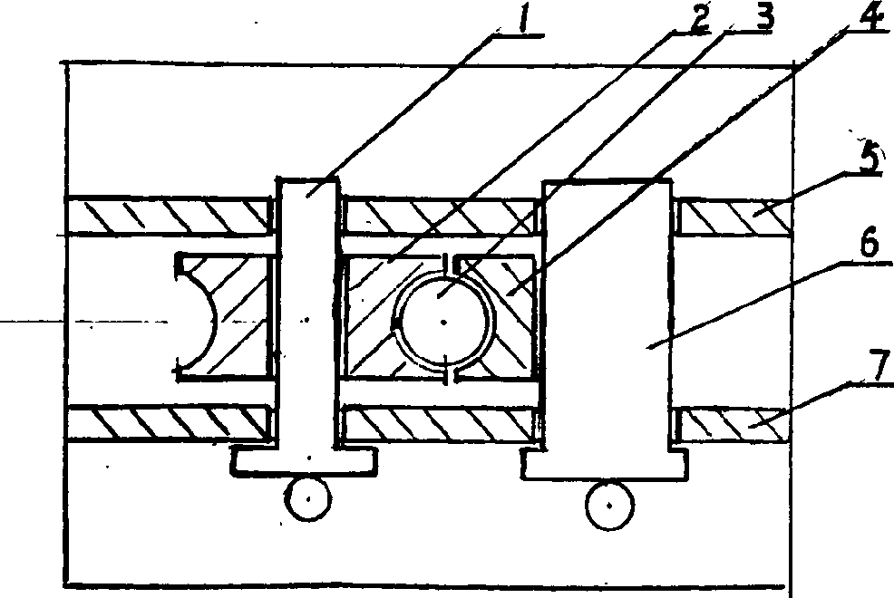
[0023] As shown in the drawings, the special equipment for bending pipes involved in the present invention includes a mold wheel 2 with a circular groove set on the frame through a rotating shaft 1, and a mold wheel 2 with a circular groove that can be clamped to a steel pipe corresponding to the position of the mold wheel 2. The template 4 of the groove, the jacket 8 that can fix the steel pipe 3 on the mold wheel 2 and the hydraulic pushing device 9 that are arranged on the frame. Template 4 of the present invention can adopt the mold wheel that has circular groove.

[0024] Taking the bent Φ219*35 high-pressure seamless steel pipe 3 for fertilizer production as an example, one end of the bent part of the steel pipe 3 is clamped on the mold wheel 2, and the exposed part of the steel pipe 3 is held tightly by the template 4 and jacketed on the exposed part of the mold wheel 2. 8. Fix firmly, and the steel pipe 3 is ready to be bent.

[0025] The other end of the bent steel p...


PUM


Abstract

The present invention relates to a manufacture method of angle pipe and its special equipment. It is characterized by that one end of steel pipe to be bent is fixed on the mould wheel, the position to be bent and deformed is tightly held by mould wheel, and another end of said steel pipe can be driven by acting force produced by hydraulic or mechanical driving device, so that the steel pipe can be moved forwards and can be bent to form angle pipe.

Description

technical field [0001] The invention relates to a method for manufacturing bent pipes for equipment in high-temperature and high-pressure industries such as fertilizer, chemical industry, petroleum, and power generation, and special equipment thereof. technical background [0002] At present, the following methods are generally used in the domestic manufacturing of elbows for high temperature and high pressure industries: [0003] 1. Fix one end of the steel pipe to be bent on the mold wheel, then squeeze the steel pipe with the auxiliary mold wheel, and turn the mold wheel to bend the steel pipe to the required angle. This method is a traditional production method for many years, and the molding process is simple and widely used. The disadvantage is that the rotation of the mold wheel requires a large power of the transmission mechanism. If the pipe is bent by this method, the outer wall of the pipe will be stretched, and the amount of thinning will be large, and waste pro...

Claims


Application Information

Patent Timeline
Patent Type & Authority Applications(China)
IPC IPC(8): B21D7/025B21D7/16
Inventor 车英年
Owner 车英年
Why Eureka
Try Eureka