Projectile motion demonstrating instrument and method

A demonstration instrument and motion technology, applied in the field of demonstration instruments about the law of projectile motion in middle school physics, to achieve the effect of convenient operation, simple structure and remarkable experimental effect

Inactive Publication Date: 2006-05-24
上海市嘉定区第二中学
View PDF0 Cites 9 Cited by
  • Summary
  • Abstract
  • Description
  • Claims
  • Application Information

AI Technical Summary

Problems solved by technology

There is no experimental demonstration teaching aid that can demonstrate the effects of these two experiments at the same time.

Method used


Image

  • Projectile motion demonstrating instrument and method
  • Projectile motion demonstrating instrument and method

Examples


Embodiment Construction

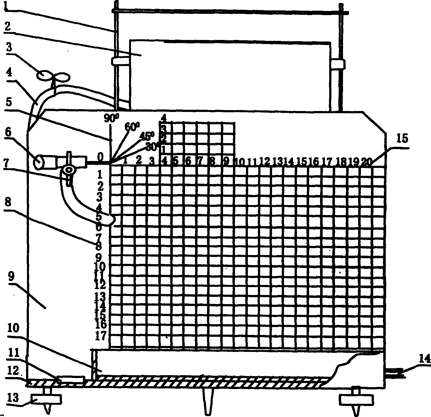
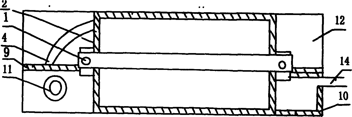
[0013] Combining the examples and figure 1 , figure 2 The structure of the present invention is described further:

[0014] This embodiment is a teacher's classroom demonstration teaching aid, because it is easy to obtain materials, simple to make, and easy to operate, it can also be used as a student's course experiment. The specific production steps are as follows:

[0015] 1. Bracket Use 3 mm metal wire to make a door-shaped frame and fix it on the panel.

[0016] 2. The water tank uses a ready-made plastic square box, with an ear seat glued on both sides, and the middle hole of the ear seat is set on the uprights on both sides of the bracket. Affects the initial velocity of the water jet.

[0017] 3. The switch is replaced by a wire clip, which is set on the outlet pipe to control the water outlet.

[0018] 4. The outlet pipe is made of latex pipe, connected to the water tank at the top and the nozzle at the bottom.

[0019] 5. The nozzle uses a large medical needle...


PUM


Abstract

Water flow is adopted in the invention as moving body. Demo instrument of projectile motion is composed of bracket, water tank, switch, outlet pipe, spray nozzle, angle adjuster, faceplate, trough for receiving water, levelmeter, motherboard, level regulation screw for motherboard, and drainpipe. The invention demonstrates regular pattern of flat throwing and inclined throwing. Comparing with former instrument by shooting off small balls, the invention possesses features of simple structure, easy of operation and high visibility.

Description

Technical field: [0001] The invention relates to an experiment demonstration instrument in the middle school classroom teaching process, in particular to a middle school physics demonstration instrument about the law of projectile motion. Background technique: [0002] When high school physics is used to teach the law and characteristics of flat throwing motion, the original supporting textbook experimental equipment is used as a demonstration experiment, and the visual effect is poor. As a student experiment, a "flat throwing motion demonstration instrument" uses multiple throws of small balls The method of connecting the track points is cumbersome to operate, and the ball must be rolled down the chute repeatedly, and the traces are connected by a curve. Students cannot intuitively observe the image curve, and the error is relatively large. Flat throwing motion is the combined motion of uniform linear motion in the horizontal direction and free fall motion in the vertical d...

Claims


Application Information

Patent Timeline
Patent Type & Authority Applications(China)
IPC IPC(8): G09B23/08
Inventor 陆林元姚成兴
Owner 上海市嘉定区第二中学
Why Eureka
Try Eureka