
Method and apparatus for producing reduced metal

A metal manufacturing and equipment technology, applied in the field of reduced metal manufacturing, can solve problems such as difficulties in regenerative combustion furnaces

Inactive Publication Date: 2006-06-07
KOBE STEEL LTD
View PDF0 Cites 4 Cited by
  • Summary
  • Abstract
  • Description
  • Claims
  • Application Information

AI Technical Summary

Problems solved by technology

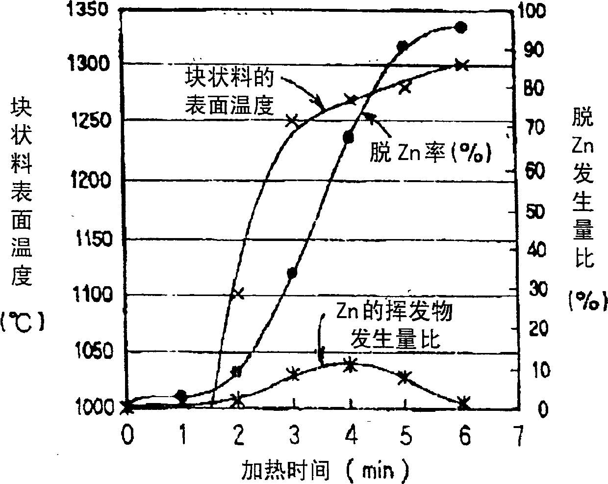
Therefore, in the first half of the reduction process at the beginning of heating, volatile substances are easy to volatilize in large quantities, and in the second half of the reduction process, in order to prevent re-oxidation and maintain a high metal rate, sufficient reducing gas must be maintained. In this case, use Regenerative combustion furnace is very difficult

Method used


Image

  • Method and apparatus for producing reduced metal
  • Method and apparatus for producing reduced metal
  • Method and apparatus for producing reduced metal

Examples


Embodiment Construction

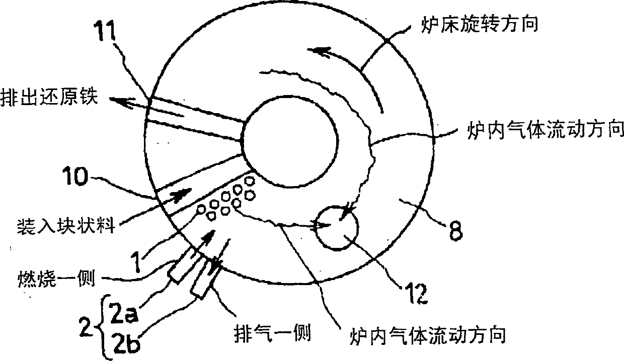
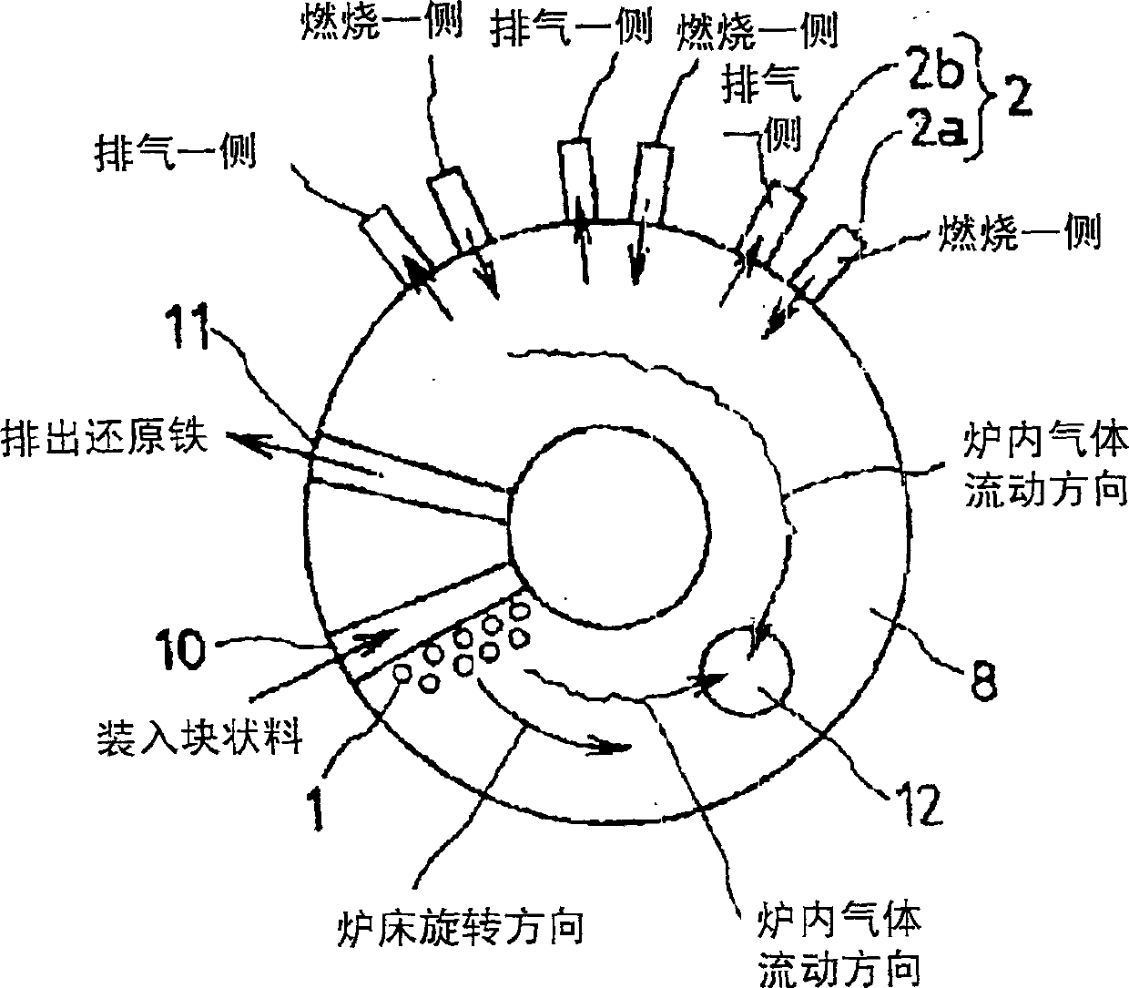
[0030] Hereinafter, referring to FIGS. 1 to 11 , an embodiment of the present invention will be described by taking reduced iron manufacturing equipment as an example.

[0031] The reduced iron manufacturing facility of the present invention uses the regenerative combustion furnace shown in Fig. 7A and Fig. 7B. The regenerative combustion furnace 2 has two intake and exhaust sections (2a, 2b). First, in the state shown in FIG. 7A , the air intake and exhaust portion 2a on one side is used as the combustion side where fuel and combustion air pass through the fuel pipeline 3 through the fuel switching valve 5a and then pass through the regenerator 7a for combustion. The other side of the suction and exhaust part 2b sucks heated air or high-temperature gas such as combustion gas on the combustion side of the suction and exhaust part 2a, passes through the regenerator 7b, and passes through the exhaust switching valve 6b from the exhaust pipe 4b to the Exhaust gas externally. At...


PUM


Abstract

A reduced metal manufacturing equipment, the combustion gas of the regenerative combustion furnace is an oxidizing gas, and the gas surrounding the carbon material block inside is a reducing gas, the regenerative combustion furnace is in a horizontal direction, and one side The combustion gas in the suction and exhaust part of the regenerative combustion furnace can realize heat storage and exhaust in the suction and exhaust part of the regenerative combustion furnace on the other side, and the regenerative combustion furnace is installed in the reduction process In the second half of the rear part, a gas discharge part is provided in front of it, and the installation position of the regenerative combustion furnace is on the process where the surface temperature of the built-in carbon block material is below 1250 ° C, and the rear of this process is provided There is a gas discharge part.

Description

technical field [0001] The present invention relates to a manufacturing device for reduced iron or reduced metal and a method for manufacturing reduced metal. The reduced iron or reduced metal is produced by putting a block of built-in carbon material made of reducing materials containing iron oxide materials or non-ferrous metal oxides and carbonaceous materials into a moving bed type reduction furnace, and then heating and reducing. Background technique [0002] The regenerative combustion furnace has two suction and exhaust parts. One suction and exhaust part is used as the combustion side by burning fuel and combustion air. High-temperature gas such as combustion gas is exhausted to the outside and used as the exhaust side. A regenerator is provided in each of these suction and exhaust parts, and the heat storage body is stored in the suction and discharge part on the exhaust side when high-temperature gas is sucked in. When the suction and discharge part on the combust...

Claims


Application Information

Patent Timeline
IPC IPC(8): C22B5/10C21B13/10C22B1/245F27B9/16F27B9/26
CPCC21B13/10C21B13/105C22B1/245C22B5/10F27B9/26Y02P10/20
Inventor 立石雅孝铁本理彦
Owner KOBE STEEL LTD
Learn More