Illuminating device and projection type video display apparatus

A lighting device and light emission technology, which is applied in projection devices, optics, instruments, etc., can solve problems such as the inability to introduce green light, and achieve the effect of reducing losses

Inactive Publication Date: 2006-06-07
SANYO ELECTRIC CO LTD
View PDF4 Cites 10 Cited by
  • Summary
  • Abstract
  • Description
  • Claims
  • Application Information

AI Technical Summary

Problems solved by technology

That is, in the illuminating device constituted by using the cross dichroic mirror 102, as Figure 10 As shown, there is a problem that the green light is cut off, so that the green light cannot be fully introduced forward

Method used


Image

  • Illuminating device and projection type video display apparatus
  • Illuminating device and projection type video display apparatus
  • Illuminating device and projection type video display apparatus

Examples


Embodiment Construction

[0030] Compare below Figure 1 to Figure 7 , the lighting device and the projection type video display device according to the embodiment of the present invention will be described.

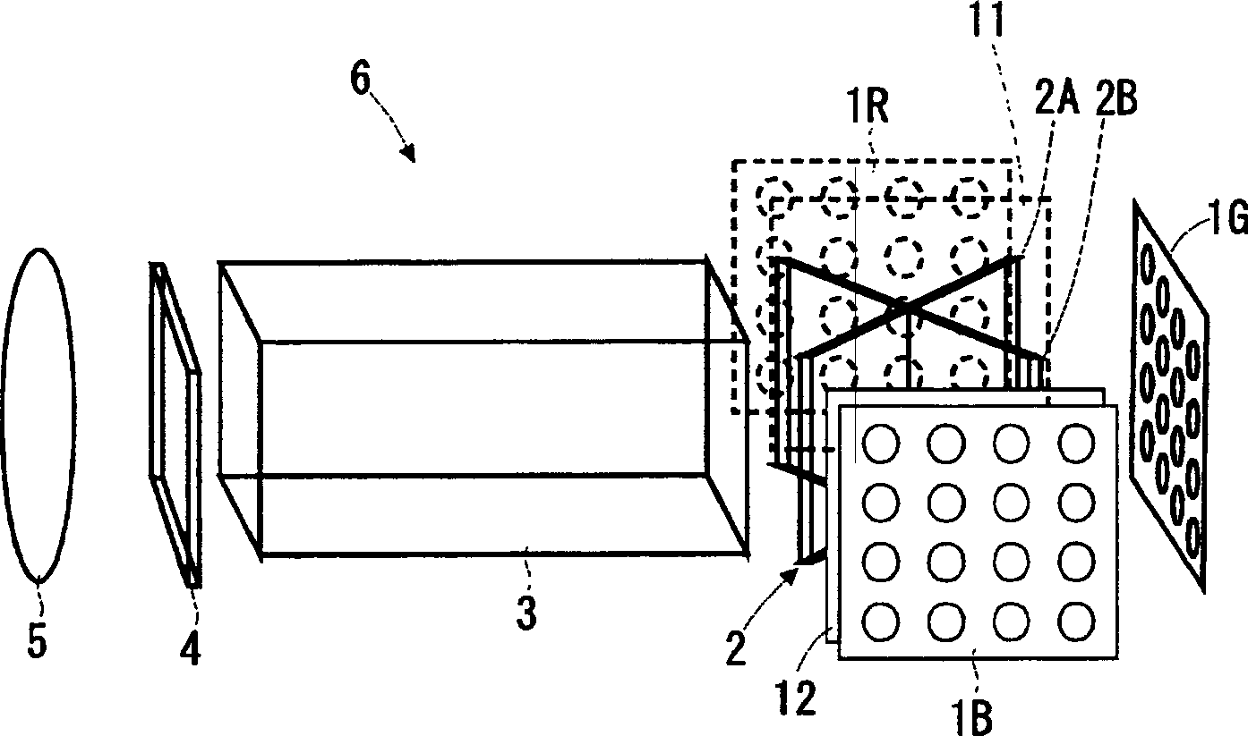
[0031] figure 1 It is a diagram showing the optical system of the single-panel projection type video display device 6 of the present embodiment. This projection type video display device 6 has three LED arrays 1R, 1G, and 1B (hereinafter, when it is not clear which LED array is referred to, a symbol "1" is used). Each LED array 1 has a structure in which LEDs (light emitting diodes) are arranged in an array. The aspect ratio of each LED array 1 may be identical or substantially identical to that of the liquid crystal display panel 4 . The LED array 1R emits red light, the LED array 1G emits green light, and the LED array 1B emits blue light. The LED array 1R, the LED array 1G, and the LED array 1B are controlled by a lighting control circuit not shown in the figure, and are sequentially turn...


PUM


Abstract

The present invention relates to an illuminating device and a projection type video display device capable of reducing the loss of each color light from each light source as much as possible. The projection type video display device (6) has three LED arrays (1R) (emitting red light), LED array (1G) (emitting green light), and LED array (1B) (emitting blue light). On the light exit side of the rod integrator (3), there are time-dividing mirrors (2A·2B) arranged in a cross shape for introducing light from each LED array into the rod integrator (3). In addition, a time-division mirror (11) is provided on the light exit side of the LED array (1R), and a time-division mirror (12) is provided on the light exit side of the LED array (1B). The time-sharing mirror switches reflection and transmission by the presence or absence of voltage loading. At the time-division lighting time of the LED arrays (1R, 1G, 1B), the reflection and transmission of the above-mentioned time-division mirror are switched, and at the same time, the video signals for each color video are supplied to the liquid crystal display panel (4) in time-division.

Description

technical field [0001] The invention relates to an illuminating device and a projection type video display device. Background technique [0002] Illumination devices used in liquid crystal projectors and the like generally consist of lamps such as ultra-high pressure mercury lamps, metal halide mercury lamps, and xenon lamps, and parabolic reflectors that parallelize their irradiated light. In addition, in the above-mentioned lighting device, in order to reduce the unevenness of the light quantity on the irradiated surface, it has an integrating function constituted by a pair of fly-eye lenses (using an optical device to form a plurality of lighting areas of a given shape in a plane, superimposed and focused) function of light on the object to be illuminated). In addition, in recent years, attempts have been made to use light emitting diodes (LEDs) as light sources (see Patent Documents 1 and 2). Also, a configuration has been proposed in which red light from a red LED, gr...

Claims


Application Information

Patent Timeline
Patent Type & Authority Applications(China)
IPC IPC(8): G03B21/20G02B27/18
Inventor 前田诚池田贵司
Owner SANYO ELECTRIC CO LTD
Why Eureka
Try Eureka