

Luminous device
A light-emitting device and light-emitting unit technology, which can be applied to lighting devices, display devices, lighting auxiliary devices, etc., and can solve the problems of lack of interest and single luminous effect
- Summary
- Abstract
- Description
- Claims
- Application Information
AI Technical Summary
Problems solved by technology
Method used
Image

Examples
Embodiment 1
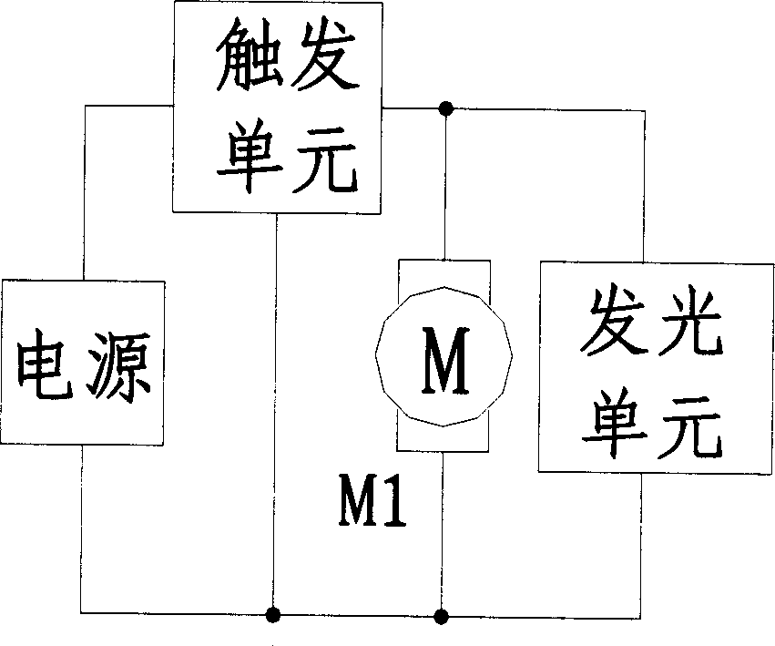
[0018] The light emitting circuit device of the present invention, such as figure 1 , including a power supply 1 , a trigger unit 3 , and a light emitting unit 2 , the power supply 1 supplies the light emitting unit 2 through the trigger unit 3 , and a motor 4 is connected in parallel with the light emitting unit 2 .
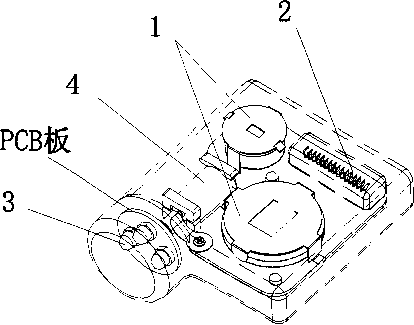
[0019] figure 2 is a schematic perspective view of this embodiment, Figure 5 It is an exploded view of this embodiment, as shown in the figure, a PCB board is fixed on the bottom shell of the present invention, and a power supply, a trigger unit and a motor are respectively fixed on the PCB board. Power supply 1, trigger unit 2, light emitting unit 3 according to figure 1 The connection mode shown in the block diagram is connected, and the motor 4 is connected in parallel with the light emitting unit in the circuit. A connecting shaft 6 is fixed on the transmission shaft 5 of the motor 4 powered by the power supply 1, and the connecting shaft 6 is connect...
Embodiment 2
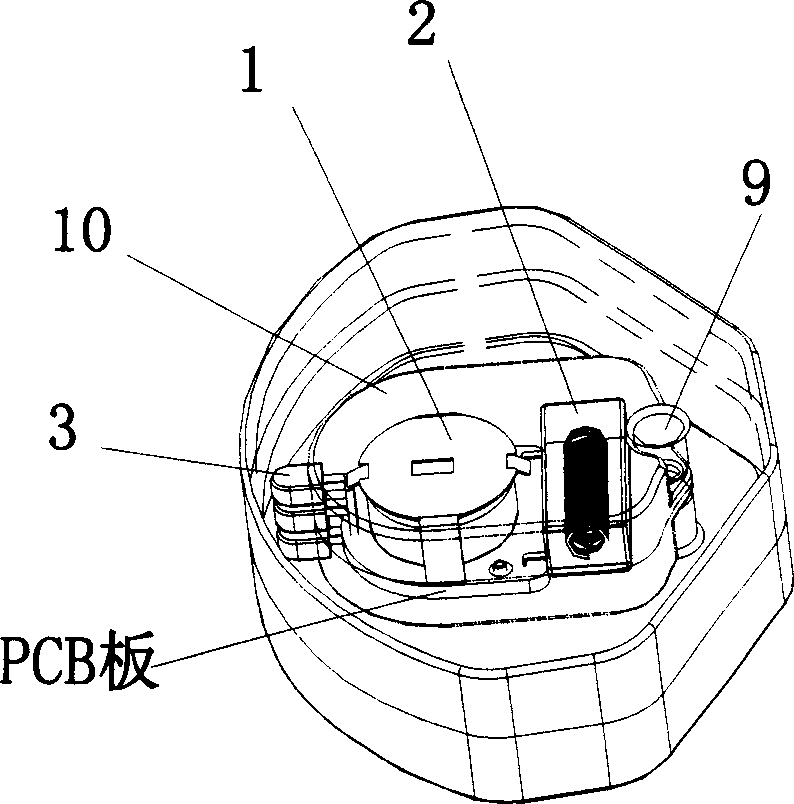
[0029] image 3 It is a three-dimensional schematic diagram of this embodiment, including a swing shaft 9 and a pendulum 10. The pendulum includes a power supply 1, a trigger unit 2, and a light-emitting unit 3. The power supply 1 supplies the light-emitting unit 2 through the trigger unit 3. When the pendulum 10 When the force swings, the light-emitting unit 3 emits light due to the operation of the trigger unit 2 and swings along the swing axis 9 to obtain a more beautiful light-emitting effect than the light-emitting device composed of fixed light-emitting units; adjust the shape of the light-emitting unit or The position of the light-emitting unit, or the brightness or flickering frequency of the light-emitting unit, can also obtain some more beautiful light-emitting effects such as solid line monochrome or multi-color arcs, dotted line monochrome or multi-color arcs, and the like.
[0030] Corresponding changes are made in the circuit connection part, which can be easily ...
Embodiment 3
[0032] Figure 4It is a three-dimensional schematic diagram of this embodiment, the rolling mechanism includes a power source 1, a trigger unit 2, and a light emitting unit 3, and the power source 1, trigger unit 2, and light emitting unit 3 are integrated to form a circular or quasi-circular structure 11 , when the circular or quasi-circular structure 11 is subjected to an external force, the trigger unit 2 works to make the light emitting unit 3 emit light and make a rolling motion, so that a more beautiful light emitting effect than a light emitting device composed of fixed light emitting units can be obtained ;Adjust the shape of the light-emitting unit or the position of the light-emitting unit, or the brightness or flashing frequency of the light-emitting unit, and you can also get some solid line monochrome or colorful concentric circles, arcs, dotted line monochrome or colorful concentric circles, arcs Wait for a more beautiful lighting effect.
[0033] Corresponding ...
PUM
 Abstract
Description
Claims
Application Information