Wiring structure of transmission wire in high speed printed circuit board

A high-speed printing and transmission line technology, applied to printed circuit components, electrical connection printed components, electrical components, etc., can solve the problems of poor signal quality, ringing and overshoot, etc., to solve crosstalk and overshoot, and improve transmission quality Effect

Inactive Publication Date: 2006-06-07
HONG FU JIN PRECISION IND (SHENZHEN) CO LTD +1
View PDF0 Cites 2 Cited by
  • Summary
  • Abstract
  • Description
  • Claims
  • Application Information

AI Technical Summary

Problems solved by technology

It can be seen from the figure that the signal quality is poor, and the phenomenon of ringing and overshoot is serious

Method used


Image

  • Wiring structure of transmission wire in high speed printed circuit board
  • Wiring structure of transmission wire in high speed printed circuit board
  • Wiring structure of transmission wire in high speed printed circuit board

Examples


Embodiment Construction

[0015] The present invention will be further described in detail below in conjunction with the accompanying drawings and specific embodiments.

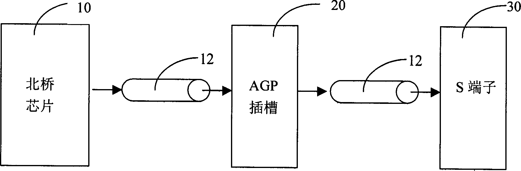
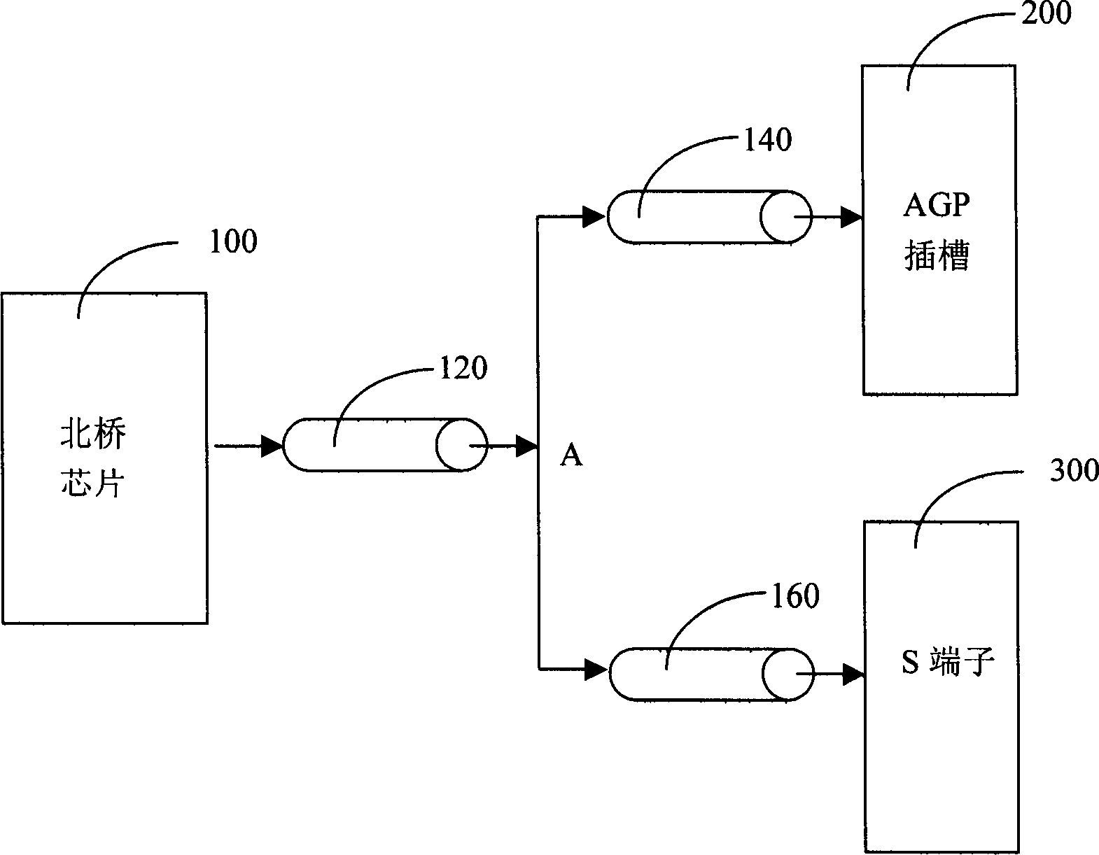
[0016] see image 3 , is a simple schematic diagram of the T-shaped wiring structure of the present invention. The present invention adopts a symmetrical topological structure. In a printed circuit board, the signal generated by the north bridge chip 100 is transmitted through a transmission line 120, and is divided into two branches 140 and 160 at a connection point A to the AGP slot 200 and the S terminal respectively. 300 pass. In the first embodiment of the present invention, the length of the transmission line 120 is 500 mils, and the lengths of the transmission lines 140 and 160 are both 3000 mils. If only one of the AGP slot or the S terminal is installed on the printed circuit board, as when only the AGP slot is installed and the S terminal is empty, a unit signal sent from the north bridge chip is transmitted along the tran...


PUM


Abstract

This invention relates to a transmission line distribution structure in high speed printed circuit board, which is in the connection of north bridge chip, AGP slot and S terminal, said north bridge chip connected with AGP slot and S terminal by T type topological transmission line structure. Said invention can effectively solves the crosstalk and overshoot problems in current line distribution structure and raises the signal transmission quality.

Description

【Technical field】 [0001] The present invention relates to a wiring structure of a transmission line in a high-speed printed circuit board, in particular to a north bridge chip, an AGP (Accelerated Graphics Port, accelerated graphics interface) slot and an S terminal (abbreviation for S-Video, dedicated input for video signals) Output interface) to reduce the transmission line routing structure of signal integrity problems. 【Background technique】 [0002] The development of electronic technology makes the IC (integrated circuit) work faster and faster, and the frequency is higher and higher. When the interconnection delay of the signal is greater than 20% of the edge signal flipping threshold time, the signal line on the PCB (printed circuit board) The transmission line effect will appear, that is, the connection line is no longer a simple wire showing lumped parameters, but a distributed parameter effect, which is high-speed design. [0003] With the development of semicond...

Claims


Application Information

Patent Timeline
Patent Type & Authority Applications(China)
IPC IPC(8): H05K1/11H05K13/06
Inventor 许寿国
Owner HONG FU JIN PRECISION IND (SHENZHEN) CO LTD
Why Eureka
Try Eureka