Trapped vortex combustor

A burner, vortex type technology, applied in the direction of combustion chamber, combustion equipment, combustion method, etc.

Inactive Publication Date: 2011-12-07
DRESSER RAND CO
View PDF0 Cites 0 Cited by
  • Summary
  • Abstract
  • Description
  • Claims
  • Application Information

AI Technical Summary

Problems solved by technology

However, challenges have existed in the fuel introduction methodology and the configuration of the flame holder that ensures performance (including acceptable emissions and acoustic stability) while reducing capital and operating costs

Method used


Image

  • Trapped vortex combustor
  • Trapped vortex combustor
  • Trapped vortex combustor

Examples


Embodiment Construction

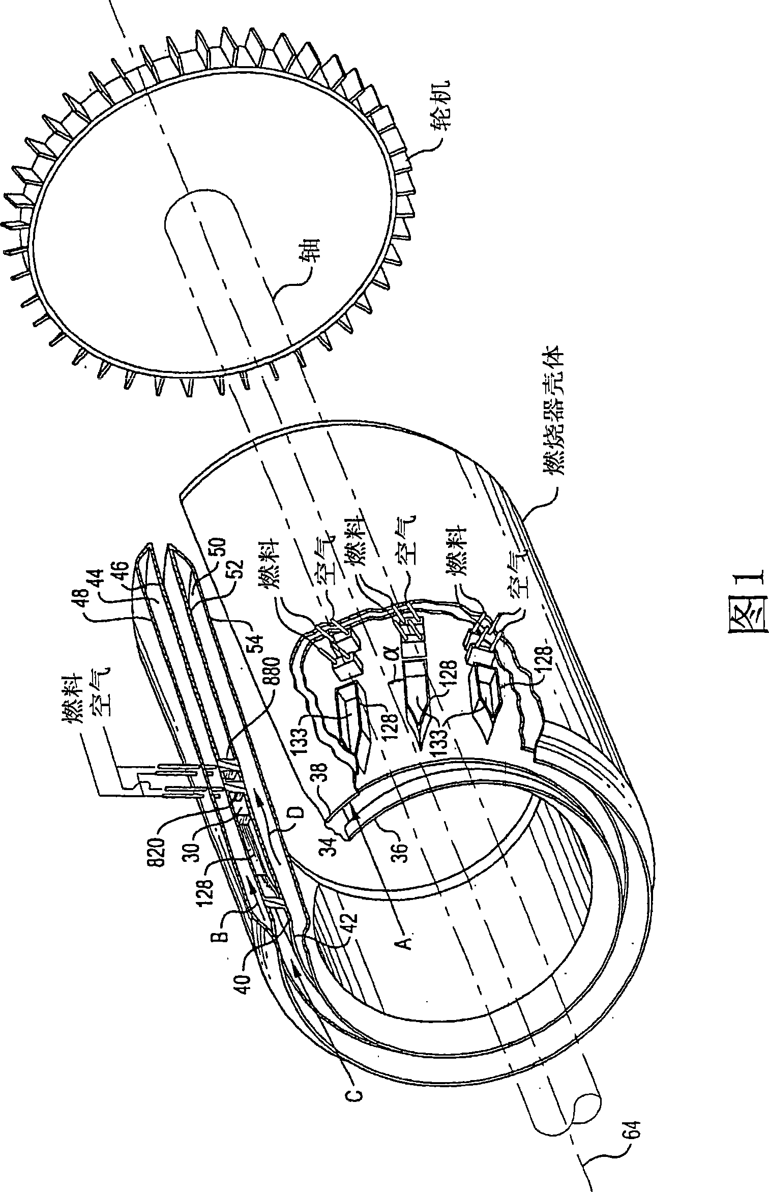
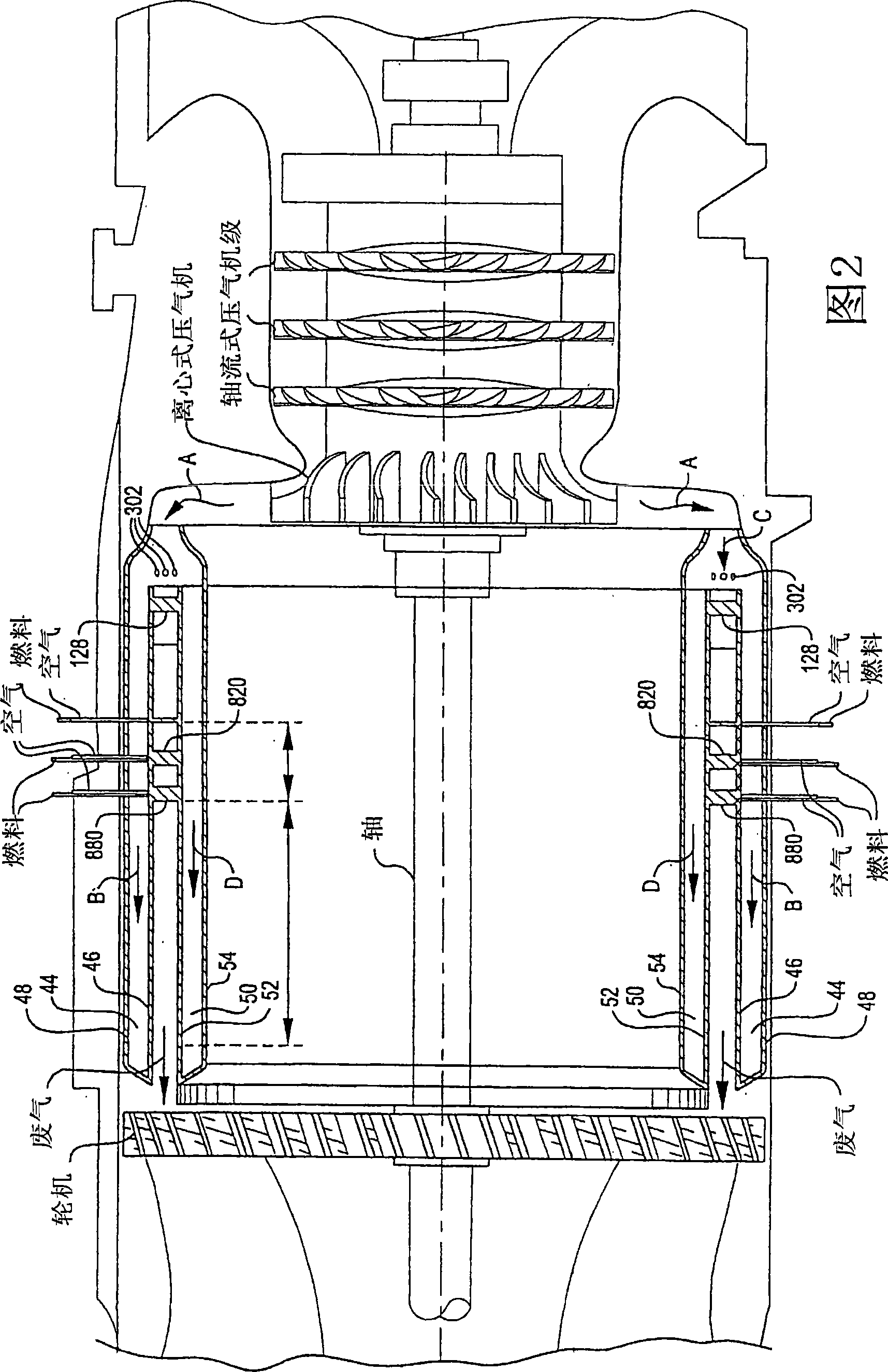
[0049] figure 1 A detailed view of an exemplary embodiment of a shut-off vortex combustor 30 for a gas turbine is provided. An inlet fluid, typically compressed air A, indicated by the reference letter A, is delivered through an inlet 34 defined between an inner inlet wall 36 and an outer inlet wall 38 . Downstream of the inlet 34, the inlet fluid A is divided into three streams, an external cooling air supply flow B, a combustion air supply flow C and an internal cooling air supply flow D. The leading edges 40 and 42 thus separate the incoming air. An external cooling air supply flow is contained within an outer plenum 44 defined between a combustor outer wall 46 and an outer plenum wall 48 . An internal cooling air supply flow D is contained between the inner plenum 50 defined between the inner combustor wall 52 and the inner plenum wall 54 . As shown, each of the walls 48, 46, 52 and 54 are placed in a solid portion by a tubular cylindrical portion of the desired diamete...


PUM


Abstract

A trapped vortex combustor for gas turbine engines. An annular combustor housing is provided having a plurality of inlet centerbodies disposed along a helical axis. The inlet centerbodies include a leading edge structure, opposing sidewalls, a pressurizable cavity, and a rear wall. Inlet centerbodies cooperate with adjacent structure and an aft bluff body to define a trapped vortex cavity combustion chamber for mixing an inlet fluid and burning fuel to form hot combustion gases. Mixing is enhanced by utilizing struts adjacent to the rear wall to create eddies in the fluid flow, and by injecting fuel and / or air in opposition to swirl created by the bulk fluid flow. Hot combustion gases are utilized in a turbine for extraction of kinetic energy, or in heat exchange equipment for recovery of thermal energy. High combustion efficiencies and less than 10 ppm emissions of oxides of nitrogen and of carbon monoxide are achieved.

Description

technical field [0001] The invention relates to the technical field of combustion. More particularly, the invention relates to the design of combustors, especially for use in gas turbines. Background technique [0002] Gas turbines have been widely used as the main prime mover in stationary power stations. However, improvements in combustion efficiency are needed, which would be particularly beneficial in order to reduce emissions. In various attempts to achieve this improvement, various methods and structures, both experimental and commercial, have been attempted. Some of these attempts have included utilizing recirculation zones to provide a continuous source of ignition by mixing hot combustion products with an input fuel and air mixture. Structural devices such as swirl vanes, bluff bodies, and rearward facing steps have generally been employed in establishing the recirculation zone to stabilize the flame. However, challenges have existed in the fuel introduction met...

Claims


Application Information

Patent Timeline
Patent Type & Authority Patents(China)
IPC IPC(8): F23R3/58F23R3/18F23R3/20F01D1/02F01D1/32F02C3/16F02K7/00F02K7/10F23RF23R3/28F23R3/50
CPCF02K7/10F05D2250/25F01D1/026F23R3/28F02K7/005F01D1/32F02C3/165F23R3/50F05D2220/60F23R3/18
Inventor 唐纳德·肯德里克肖恩·P·劳勒罗伯特·C·斯蒂尔
Owner DRESSER RAND CO
Why Eureka
Try Eureka