Projector system

A technology for a projector and a relay system, applied in the field of projector systems, can solve the problems of expensive polarization conversion systems and difficulty in obtaining high quality, and achieve the effect of cost reduction

Inactive Publication Date: 2006-06-07
KONINKLIJKE PHILIPS ELECTRONICS NV
View PDF1 Cites 6 Cited by
  • Summary
  • Abstract
  • Description
  • Claims
  • Application Information

AI Technical Summary

Problems solved by technology

The polarization conversion system is a very expensive system and for such a system it is difficult to obtain and maintain high quality

Method used


Image

  • Projector system
  • Projector system
  • Projector system

Examples


Embodiment Construction

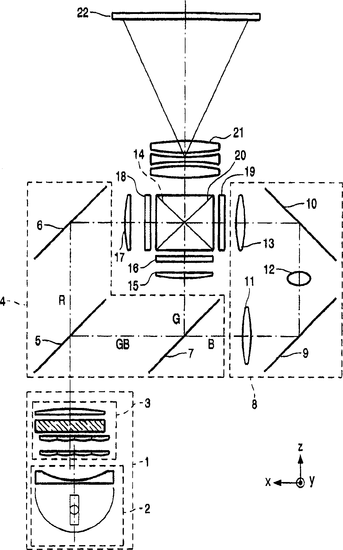
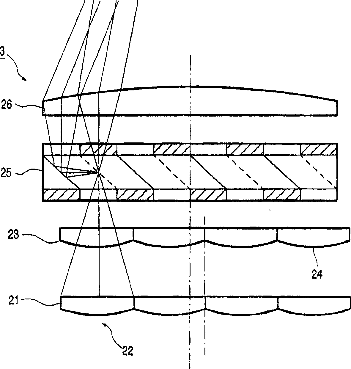
[0025] figure 1 A projector system known from the prior art is shown. The projector system comprises an illumination optics system 1 comprising a lamp and a parabolic projector 2 . The light emitted by the lamp passes through a polarization conversion system (PCS) 3 . The system converts the unpolarized light emitted by the lamp into polarized light. figure 2 One way to change unpolarized light into polarized light is explained in . The light is split into three colored beams in a color separation system 4 comprising a number of (semi-transparent) mirrors 5 , 7 and a folding mirror 6 . In one light path of the known system, the blue light is relayed via a relay system 8 with a number of mirrors 9 , 10 and a number of relay lenses 11 , 12 , 13 . The three kinds of light beams are incident on the modulators 16, 18 and 19 through the lenses 13, 15 and 17, and the said colored light beams are modulated by these modulators. The light beams are recombined in the color combiner...


PUM


Abstract

A projector system comprising an illumination optical system (1), a color separation system (4) for separating light from the illumination optical system (1) into at least three colored light beams (R, G, B), the system further A modulation device (16, 18, 19) for modulating the colored beams is included for each colored beam, and a color combiner (20) for combining the modulated colored beams. The projector system includes a polarization conversion system (PCS) for at least one color beam and does not include a polarization conversion system for at least one other color beam.

Description

technical field [0001] The present invention relates to a projector system comprising an illumination optical system, a polarization conversion system, a color separation system for separating light from the illumination optical system into at least three colored beams, the system further comprising a A modulation device for modulating the colored light beams, and a color combiner for combining the modulated colored light beams. Background technique [0002] Such a device is known from European Patent Application No. 1071292. [0003] A projector typically includes an illumination optical system, a color separation system, and a modulation device (such as a liquid crystal panel) for modulating colored light beams. The modulated colored beams are then combined and projected onto the screen through a projection lens or lens system. If these modulators add image information to the light beam by means of polarization modulation, the modulator, such as a liquid crystal display ...

Claims


Application Information

Patent Timeline
Patent Type & Authority Applications(China)
IPC IPC(8): H04N9/31
CPCG02B27/1046G02B27/145G02B27/149G02B27/285H04N9/3105H04N9/3167
Inventor A·J·S·M·德瓦安
Owner KONINKLIJKE PHILIPS ELECTRONICS NV
Why Eureka
Try Eureka